
Safety device for stamping die debugging

A technology of safety device and stamping die, which is applied in the field of stamping dies, can solve the problems that affect the stamping production efficiency of die loading, cumbersome process, loose slider and crushing damage, etc., achieve fast and accurate die loading height, avoid crushing damage, and improve efficiency Effect

Active Publication Date: 2021-04-06
钜隆模具(东莞)有限公司
View PDF9 Cites 0 Cited by
  • Summary
  • Abstract
  • Description
  • Claims
  • Application Information

AI Technical Summary

Problems solved by technology

[0007] Aiming at the deficiencies of the prior art, the present invention provides a safety device for stamping die debugging, which can quickly and accurately adjust the height of the die, and avoid the risk of crushing caused by loose sliders of the press, thereby improving the efficiency of stamping die assembly and production , the advantages of ensuring the life and health of the workers, solve the cumbersome process of adjusting the height many times due to the inappropriate height of the mold, and the frequent loosening and tightening of the fastening nut of the slider of the press is easy to cause the slider to loosen and hurt the workers, thus affecting the mold loading And the problem of stamping production efficiency

Method used


Image

  • Safety device for stamping die debugging
  • Safety device for stamping die debugging
  • Safety device for stamping die debugging

Examples


Embodiment Construction

[0025] The following will clearly and completely describe the technical solutions in the embodiments of the present invention with reference to the accompanying drawings in the embodiments of the present invention. Obviously, the described embodiments are only some, not all, embodiments of the present invention. Based on the embodiments of the present invention, all other embodiments obtained by persons of ordinary skill in the art without making creative efforts belong to the protection scope of the present invention.

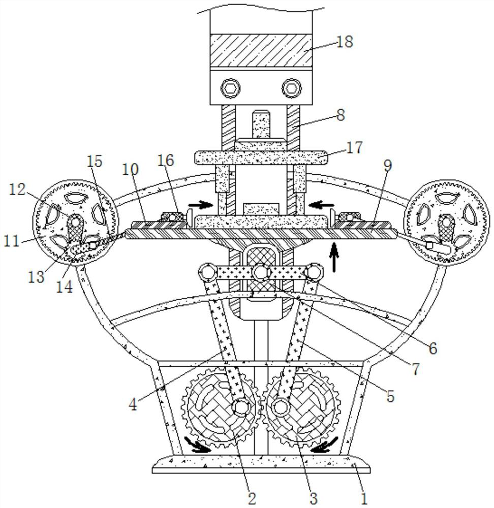
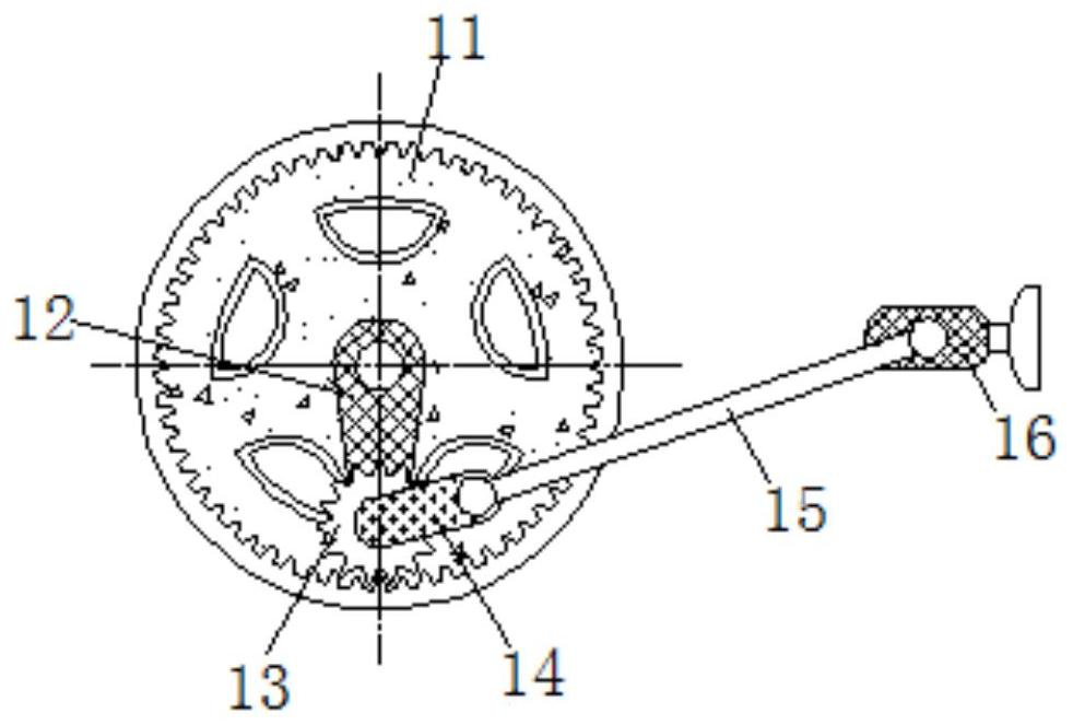
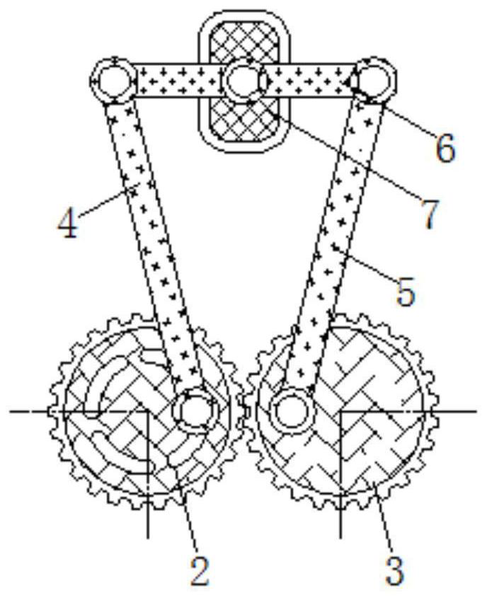
[0026] see Figure 1-4 , a safety device for stamping die debugging, including a base bracket 1, a first gear 2 is rotatably connected to the inside of the base bracket 1, the first gear 2 and the second gear 3 have the same size and specification, and are meshed with each other, and the base bracket 1 The inside is rotatably connected with the second gear 3, the surface of the first gear 2 is rotatably connected with the first push rod 4, the length of the fi...


PUM


Abstract

The invention relates to the technical field of stamping dies, and discloses a safety device for stamping die debugging. The safety device for the stamping die debugging comprises a base support, a first gear is rotatably connected to the interior of the base support, a second gear is rotatably connected to the interior of the base support, and a first push rod is rotatably connected to the surface of the first gear. According to the safety device for the stamping die debugging, a first sliding block slides on the surface of a first guide rail, and the first sliding block slides to drive a workbench fixedly connected with the surface of the first sliding block to move, so that the height of the workbench is adjusted, and the height between a stamping die mechanism and a pressing machine sliding block mechanism is made to be in a proper state; a second sliding block slides on the surface of a second guide rail, and then the stamping die mechanism is clamped through a clamping block arranged on the surface of the second sliding block, so that the effects that the die filling height is quickly and accurately adjusted, the risk of bruising caused by loosening of the pressing machine sliding block is avoided, the stamping die assembling and production efficiency is improved and the life health of operators is guaranteed are achieved.

Description

technical field [0001] The invention relates to the technical field of stamping dies, in particular to a safety device for debugging stamping dies. Background technique [0002] The installation and debugging of stamping dies must be particularly careful, especially for medium and large dies, which are not only expensive, but also heavy, and there is a risk of being pinched and crushed if you are not careful. [0003] When the existing punching die is installed on the punching machine, the punch press slider mechanism is manually moved to a suitable position, and then the die handle of the punching die in the mold clamping state is placed in the groove of the press slider mechanism. Adjust the gap between the mold and the slider of the press. During this period, it is necessary to adjust the lifting and fastening nuts of the connecting rod of the slider of the press several times to achieve a suitable mold installation height. The above is the first and most critical step of...

Claims


Application Information

Patent Timeline
Patent Type & Authority Applications(China)
IPC IPC(8): B21D22/02B21D37/10B21D37/14
CPCB21D22/02B21D37/10B21D37/14
Inventor 谢志军胡杰伟黄喜
Owner 钜隆模具(东莞)有限公司
Learn More