


Quick Research
Generate reliable direction feasibility study reports for your R&D in just a few steps.

Technical Q&A
Discover and master advanced knowledge NOW. Basics, ideas, possibilities, all at once.

Find Solutions
As an expert in R&D theories, this can generate solutions to your technical problems instantly.

Evaluate Feasibility
Analyze your overall solution with one click, know your potential R&D risks in advance.

Monitor Landscape
Get weekly tech updates, stay abreast of the latest tech innovations and key insights.
A control method and device for a hair removal instrument
A control method, technology of hair removal device, applied in parts of surgical instruments, medical science, surgery, etc., can solve problems such as poor heat dissipation of hair removal device, and achieve the effect of reducing power
- Summary
- Abstract
- Description
- Claims
- Application Information
AI Technical Summary
Problems solved by technology
Method used
Image


Examples
Embodiment 1
[0033] According to an embodiment of the present invention, an embodiment of a method for controlling a hair removal instrument is provided. It should be noted that the steps shown in the flow chart of the accompanying drawings can be executed in a computer system such as a set of computer-executable instructions, and, Although a logical order is shown in the flowcharts, in some cases the steps shown or described may be performed in an order different from that shown or described herein.
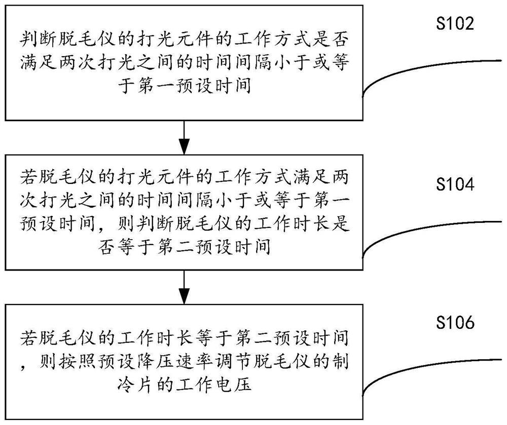
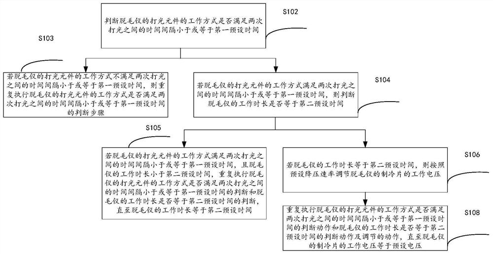
[0034] figure 1 It is a flow chart of a control method of a hair removal instrument according to an embodiment of the present invention, such as figure 1 As shown, the method includes the following steps:
[0035] Step S102, judging whether the working mode of the lighting element of the hair removal device satisfies that the time interval between two lightings is less than or equal to the first preset time;
[0036] Step S104, if the working mode of the lighting element of the hair remova...
Embodiment 2
[0066] The embodiment of the present invention also provides a control device for a hair removal instrument, the control device for the hair removal instrument is used to implement the control method for the hair removal instrument provided in the above-mentioned content of the embodiment of the present invention, the following is the description of the hair removal instrument provided by the embodiment of the present invention A detailed description of the control device.
[0067] Such as Figure 5 as shown, Figure 5 It is a schematic diagram of the control device of the above-mentioned hair removal instrument, and the control device of the hair removal instrument includes: a first judger 10 , a second judger 20 and a regulator 30 .
[0068] The first determiner 10 is used to determine whether the working mode of the lighting element of the hair removal device satisfies whether the time interval between two lightings is less than or equal to the first preset time;
[0069]...
Embodiment 3
[0079] An embodiment of the present invention also provides an electronic device, including a memory and a processor, the memory is used to store a program that supports the processor to execute the method described in the first embodiment above, and the processor is configured to execute the program stored in memory.
[0080] see Figure 6 , the embodiment of the present invention also provides an electronic device 100, including: a processor 50, a memory 51, a bus 52 and a communication interface 53, the processor 50, the communication interface 53 and the memory 51 are connected through the bus 52; Executable modules, such as computer programs, stored in the execution memory 51 .
[0081] Wherein, the memory 51 may include a high-speed random access memory (RAM, Random Access Memory), and may also include a non-volatile memory (non-volatile memory), such as at least one disk memory. The communication connection between the system network element and at least one other net...
PUM
 Abstract
Description
Claims
Application Information
 - R&D Engineer
- R&D Manager
- IP Professional
- Industry Leading Data Capabilities
- Powerful AI technology
- Patent DNA Extraction
Browse by: Latest US Patents, China's latest patents, Technical Efficacy Thesaurus, Application Domain, Technology Topic, Popular Technical Reports.
© 2024 PatSnap. All rights reserved.Legal|Privacy policy|Modern Slavery Act Transparency Statement|Sitemap|About US| Contact US: help@patsnap.com