Conveying belt abrasion state detection method and system based on binocular shooting

A wear state and detection method technology, applied in image data processing, instruments, calculations, etc., can solve problems such as deterioration, wear on the surface of the conveyor belt, and the inability to detect and determine the wear position and wear degree of the conveyor belt

Pending Publication Date: 2021-04-02
慧之安信息技术股份有限公司
View PDF0 Cites 3 Cited by
  • Summary
  • Abstract
  • Description
  • Claims
  • Application Information

AI Technical Summary

Problems solved by technology

[0002] At present, in industrial production, conveyor belts are used as the item conveying tool of the assembly line. Through the conveyor belt, the items can be transported to the corresponding location area for processing according to the predetermined path, thereby improving the efficiency of industrial production. At the same time, the conveyor belt will be in operation. Friction with the transmission mechanism will cause different degrees of wear on the surface of the conveyor belt. If the wear on the surface of the conveyor belt is not dealt with in time, the wear on the surface of the conveyor belt will further deteriorate, thus affecting the normal conveying action of the conveyor belt
The existing technology can only track and shoot the conveyor belt, and manually screen the captured images to determine the wear position and degree of wear of the conveyor belt. This screening method inevitably has certain errors, which cannot be corrected. Accurate, timely and reliable detection and determination of the wear position and wear degree of the conveyor belt

Method used


Image

  • Conveying belt abrasion state detection method and system based on binocular shooting
  • Conveying belt abrasion state detection method and system based on binocular shooting
  • Conveying belt abrasion state detection method and system based on binocular shooting

Examples


Embodiment Construction

[0071] The following will clearly and completely describe the technical solutions in the embodiments of the present invention with reference to the accompanying drawings in the embodiments of the present invention. Obviously, the described embodiments are only some, not all, embodiments of the present invention. Based on the embodiments of the present invention, all other embodiments obtained by persons of ordinary skill in the art without creative efforts fall within the protection scope of the present invention.

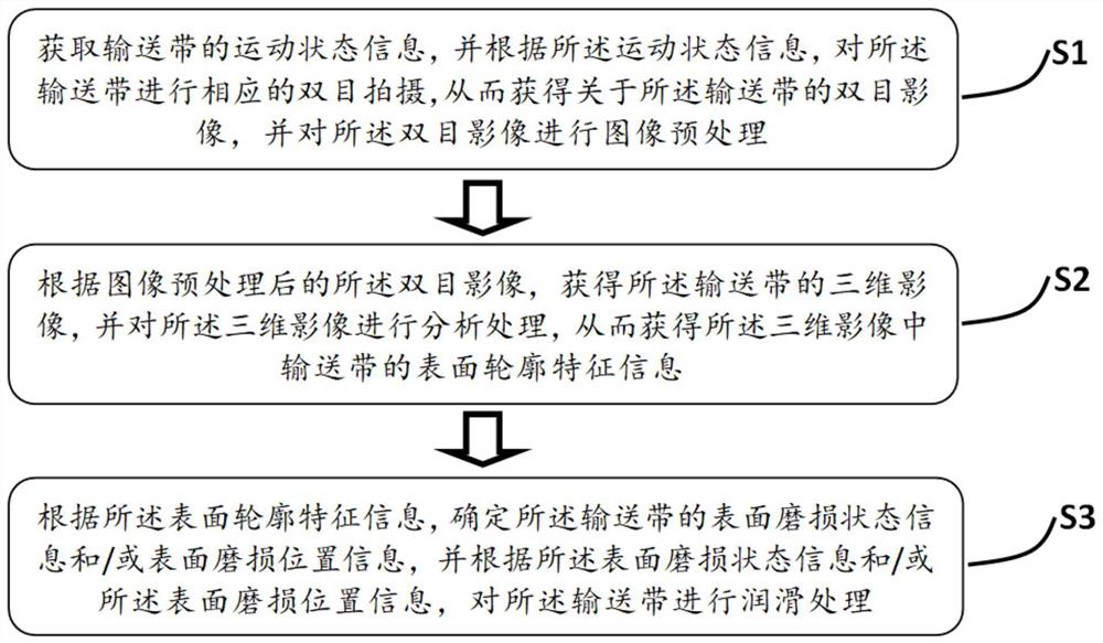
[0072] refer to figure 1 , is a schematic flowchart of a method for detecting the wear state of a conveyor belt based on binocular photography provided by an embodiment of the present invention. The method for detecting the wear state of the conveyor belt based on binocular photography includes the following steps:

[0073] Step S1: Obtain the motion state information of the conveyor belt, and perform corresponding binocular photography on the conveyor belt accord...


PUM


Abstract

The invention provides a conveying belt wear state detection method and system based on binocular shooting, and the method comprises the steps: obtaining a binocular image of a conveying belt throughshooting according to the motion state of the conveying belt, determining a three-dimensional image of the conveying belt according to the binocular image, and obtaining the surface contour feature information of the conveying belt; therefore, the surface abrasion state information and/or the surface abrasion position information of the conveying belt are/is obtained, adaptive lubricating treatment is carried out on the conveying belt, real-time binocular shooting detection can be carried out on the conveying belt while the conveying belt carries out conveying movement, and therefore the abrasion position and the abrasion degree of the conveying belt can be accurately, timely and reliably determined; therefore, the conveying movement smoothness of the conveying belt is improved.

Description

technical field [0001] The invention relates to the technical field of conveyor belt monitoring, in particular to a method and system for detecting the wear state of a conveyor belt based on binocular photography. Background technique [0002] At present, in industrial production, conveyor belts are used as the item conveying tool of the assembly line. Through the conveyor belt, the items can be transported to the corresponding location area for processing according to the predetermined path, thereby improving the efficiency of industrial production. At the same time, the conveyor belt will be in operation. Friction with the transmission mechanism will cause different degrees of wear on the surface of the conveyor belt. If the wear on the surface of the conveyor belt is not treated in time, the wear on the surface of the conveyor belt will further deteriorate, thus affecting the normal conveying action of the conveyor belt. The existing technology can only track and shoot th...

Claims


Application Information

Patent Timeline
Patent Type & Authority Applications(China)
IPC IPC(8): G06T7/55G06T7/00G06T7/13G06T7/60G06T7/73
CPCG06T5/002G06T7/0004G06T7/60G06T2207/10028G06T2207/20024G06T2207/30108G06T2207/30244G06T7/13G06T7/55G06T7/73
Inventor 杜建海兰雨晴余丹杨文昭王丹星
Owner 慧之安信息技术股份有限公司
Why Eureka
Try Eureka