
Detection device for road and bridge concrete structure and detection method thereof

A technology for concrete structures and detection devices, which is applied to measurement devices, mechanical devices, mechanical measurement devices, etc., can solve the problems of being susceptible to dust erosion, unfavorable auxiliary measurement of bridge concrete structures, and unfavorable transfer and movement of detection devices. The effect of using and convenient erection

Pending Publication Date: 2021-04-02
MCC NORTHEAST CONSTR SHENYANG ENGTECH CO LTD
View PDF0 Cites 1 Cited by
  • Summary
  • Abstract
  • Description
  • Claims
  • Application Information

AI Technical Summary

Problems solved by technology

[0003] The existing engineering measuring instruments used for bridge concrete structure testing are relatively unified and perfect in structure technology. There is no folding support frame assembly, which is not conducive to the transfer and movement of the overall testing device. It cannot be conveniently erected and fixed during the use of the testing device. The instrument cannot be stored after use, and it is easily eroded by dust. There is no rational configuration to engage the ruler, which is not conducive to the auxiliary measurement of bridge concrete structures. Therefore, it is very meaningful to design a detection device for road bridge concrete structures.

Method used


Image

  • Detection device for road and bridge concrete structure and detection method thereof
  • Detection device for road and bridge concrete structure and detection method thereof
  • Detection device for road and bridge concrete structure and detection method thereof

Examples


Embodiment Construction

[0030] The following will clearly and completely describe the technical solutions in the embodiments of the present invention with reference to the accompanying drawings in the embodiments of the present invention. Obviously, the described embodiments are only some, not all, embodiments of the present invention. Based on the embodiments of the present invention, all other embodiments obtained by persons of ordinary skill in the art without making creative efforts belong to the protection scope of the present invention.

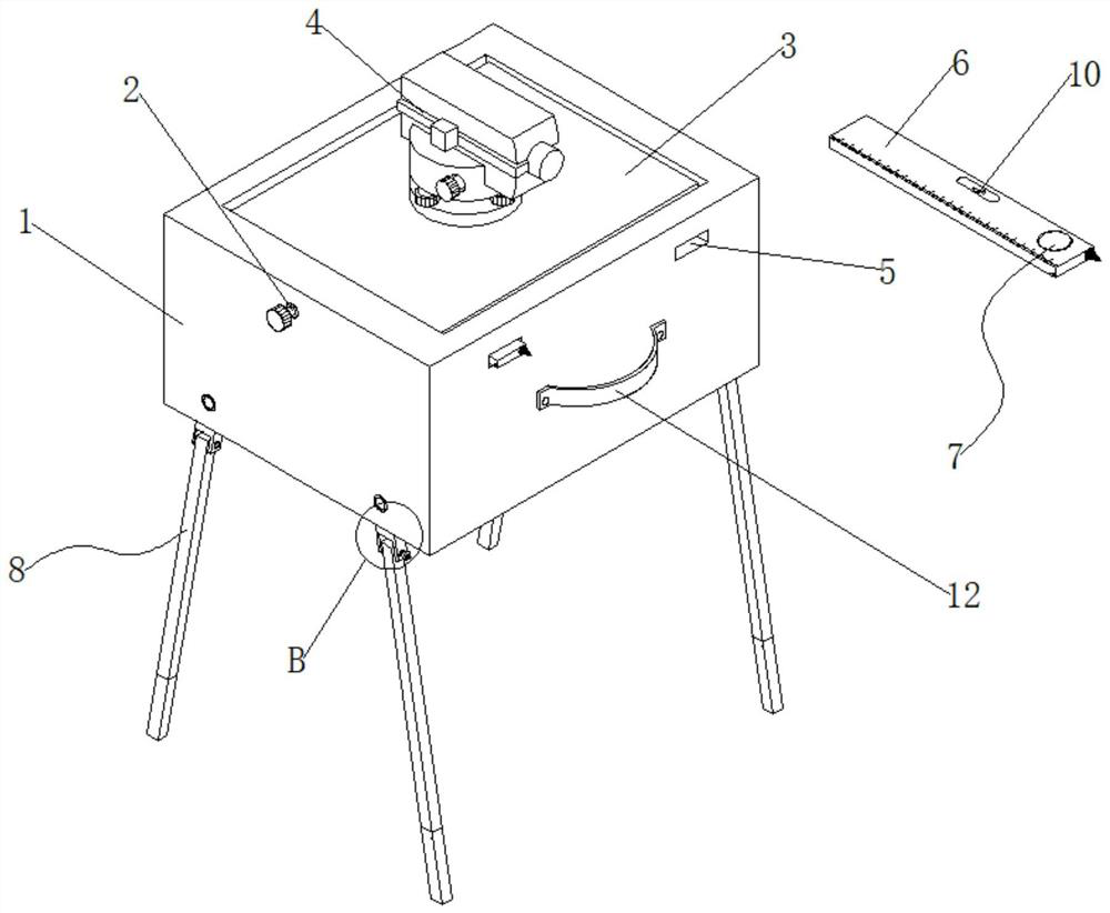
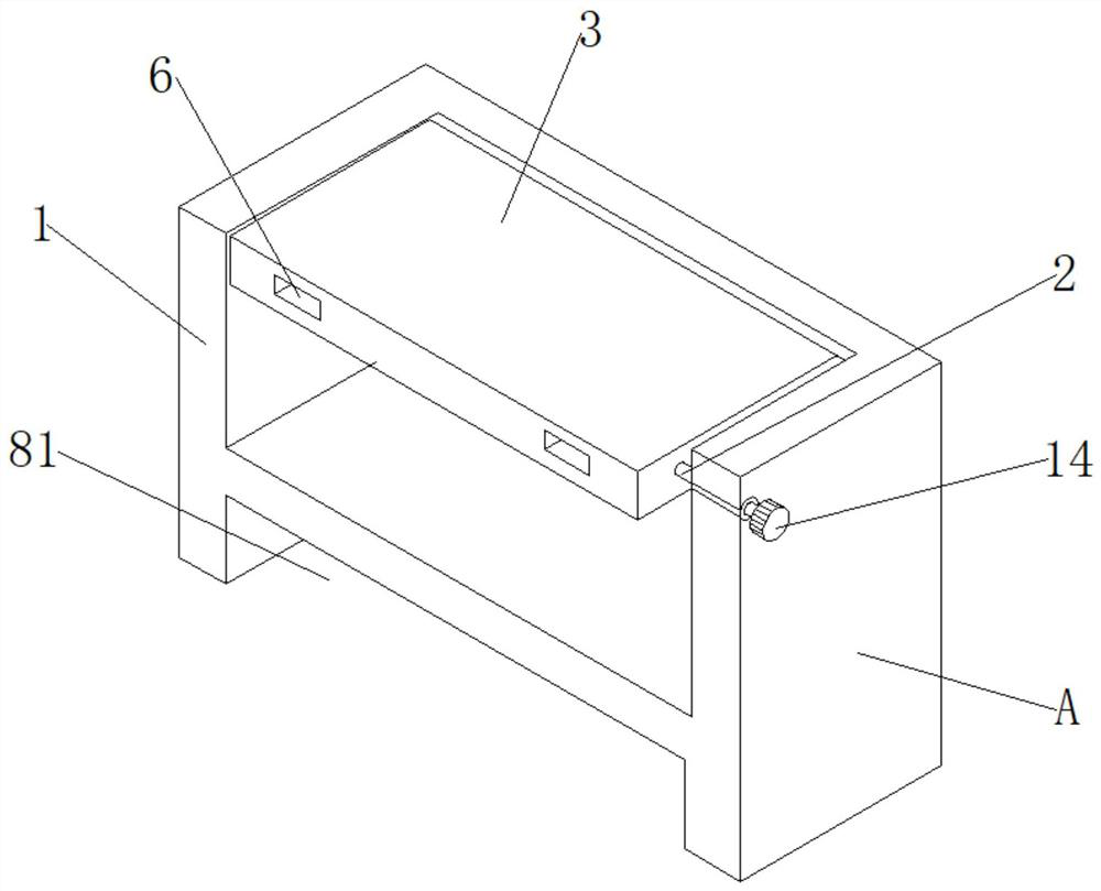
[0031] see Figure 1-6 , an embodiment provided by the present invention: a detection device for concrete structures of roads and bridges, including a mounting box 1, a fixed shaft 2, a mounting plate 3, an engineering measuring instrument 4, a socket hole 5, and a snapping ruler 6 , tape measure assembly 7, folding support frame assembly 8 and hand wheel 14, the top inner wall of installation box 1 is connected with installation plate 3 through fixed shaft 2 ...


PUM


Abstract

The invention discloses a detection device for a road and bridge concrete structure and a detection method thereof. The detection device comprises an installation box, a rotating shaft, an installation plate, an engineering measurement instrument, an insertion hole, a clamping straight ruler, a measuring tape measurement assembly, a folding support frame assembly and a hand wheel, wherein the inner wall of the top end of the installation box is rotatably connected with the installation plate through the rotating shaft; a hand wheel is fixedly connected to the end, penetrating through the exterior of the mounting box, of the rotating shaft, an engineering measurement instrument is mounted on the outer wall of the top end of the installation plate through bolts, insertion holes are correspondingly formed in the installation plate and the outer wall of one side of the installation box in a penetrating mode, clamping straight rulers are inserted into the insertion holes, and the measuringtape measurement assembly is arranged on the inner wall of one end of the clamping straight ruler. According to the detection device, the whole detection device can be transferred and moved, the measurement instrument can be stored after being used, and the problem that traditional equipment is prone to being corroded by dust is solved; the arrangement of the measuring tape measurement assembly onthe clamping straight ruler is beneficial to auxiliary measurement in the detection process of the bridge concrete structure.

Description

technical field [0001] The invention relates to the field of road and bridge detection equipment, in particular to a detection device and a detection method for road and bridge concrete structures. Background technique [0002] With the vigorous development of the transportation industry, the number of high-grade highways, mainly expressways and first-class highways, has increased year by year. Among them, road bridges are often required to be constructed during the construction of some road sections such as crossing rivers and seas. Road bridges, Generally, it is composed of several parts such as roadbed, road surface, bridge, tunnel engineering and traffic engineering facilities. The construction of road bridges generally requires concrete as a material for construction. After the construction of road bridges, it is generally necessary to test the concrete structure. Engineering measuring instruments are often used in the testing process, and the engineering measuring inst...

Claims


Application Information

Patent Timeline
IPC IPC(8): G01B5/245G01B5/24G01C9/24
CPCG01B5/24G01B5/245G01C9/24
Inventor 乔亮许洪川
Owner MCC NORTHEAST CONSTR SHENYANG ENGTECH CO LTD
Learn More