Electroplating device
An electroplating device and electrode technology, applied in the direction of electrolysis process, electrolysis components, cells, etc., can solve problems such as scattering, impact on electroplating quality and efficiency, and influence on electroplating effect of plated parts, so as to ensure uniformity and slow down the rolling speed of rods Effect
- Summary
- Abstract
- Description
- Claims
- Application Information
AI Technical Summary
Problems solved by technology
Method used
Image

Examples
Embodiment 1
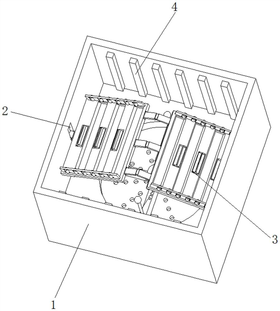
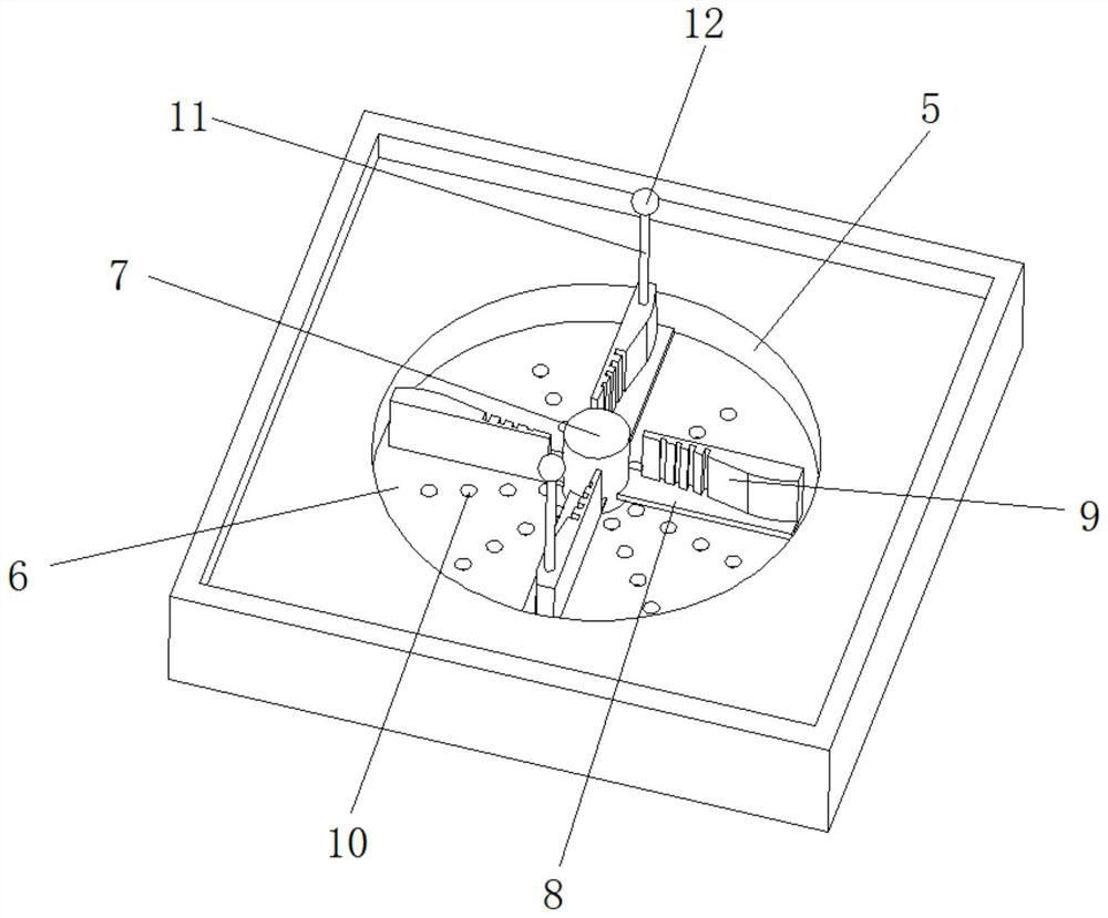
[0038] like Figure 1-2As shown, the present invention provides a technical solution: an electroplating device, including an electroplating generating tank 1, the left and right sides of the electroplating generating tank 1 are provided with adjusting chute 2, and the vertical position inside the adjusting chute 2 is slidably connected There is an electrode carrying mechanism 3, the front and back of the inside of the adjustment chute 2 are evenly and fixedly connected with the electrode rod 4, and the middle position of the inner bottom of the electroplating generating tank 1 is fixedly connected with a guide inner tank 5, and the inside of the guide inner tank 5 is fixed at a position close to the upper side A limiting baffle 6 is connected, and a motor drive shaft 7 is connected to the middle position inside the guiding inner tank 5 for rotation. The vortex generating mechanism 9 is uniformly provided with filter holes 10 on the surface of the limiting baffle 6 .
[0039] ...
Embodiment 2
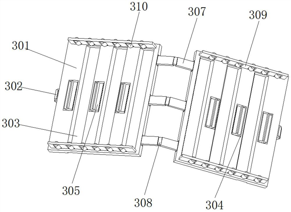
[0041] like Figure 3-6 As shown, on the basis of Embodiment 1, the present invention provides a technical solution: an electroplating device, the electrode mounting mechanism 3 includes an electrode carrier plate 301, and the outer side of the electrode carrier plate 301 is rotatably connected with a moving slider 302, and the moving slider The block 302 is slidably connected with the inside of the adjustment chute 2 , and the surface of the top of the electrode carrier plate 301 is uniformly provided with an overturning groove 303 . Avoid the phenomenon of uneven plating caused by traditional clamping on rods, and at the same time ensure that the plated parts remain energized when they roll in the device.
[0042] The top surface of the electrode carrier plate 301 and the position between the turning grooves 303 are provided with a walking restriction groove 304, the inner rotation of the walking restriction groove 304 is connected with a walking shaft 305, and the middle po...
Embodiment 3
[0048] like Figure 7 As shown, on the basis of Embodiment 1 and Embodiment 2, the present invention provides a technical solution: an electroplating device, the vortex generating mechanism 9 includes a resistance-increasing stirring rod 91, and the outer side of the resistance-increasing stirring rod 91 is fixedly connected with a guide The arc plate 92 , the bottom surface of the resistance-increasing stirring rod 91 and the guiding arc plate 92 are all fixedly connected with the stirring carrying plate 8 . The lower part of the electrolyte is circulated and stirred, and the electrolyte forms a vortex structure, which increases the fluidity of the electrolyte and ensures the uniform distribution of ions in the electrolyte. At the same time, the vortex gathers the precipitates generated by electrolysis to avoid the influence of the precipitates on the electroplating.
[0049] The front of the resistance-increasing stirring rod 91 is uniformly provided with increasing and bloc...
PUM
 Abstract
Description
Claims
Application Information
 - R&D
- Intellectual Property
- Life Sciences
- Materials
- Tech Scout
- Unparalleled Data Quality
- Higher Quality Content
- 60% Fewer Hallucinations
Browse by: Latest US Patents, China's latest patents, Technical Efficacy Thesaurus, Application Domain, Technology Topic, Popular Technical Reports.
© 2025 PatSnap. All rights reserved.Legal|Privacy policy|Modern Slavery Act Transparency Statement|Sitemap|About US| Contact US: help@patsnap.com