Metal filing treatment device for metal material machining

A metal material and processing device technology, applied in the field of metal scrap processing devices for metal material processing, can solve the problems of large metal scraps affecting the compression effect, low yield, large volume, etc. The effect of improving processing efficiency

Inactive Publication Date: 2021-04-02
恒凌金属制品(湖州)有限公司
View PDF6 Cites 0 Cited by
  • Summary
  • Abstract
  • Description
  • Claims
  • Application Information

AI Technical Summary

Problems solved by technology

[0002] With the development of the national economy, various fields are developing at a high speed, and many processing plants have sprung up. Metal product processing plants are particularly prosperous. With the expansion of metal processing plants, various large-scale metal processing equipment are in operation. However, the processing of metal products will inevitably cause a lot of metal waste, which will pollute the environment of the processing plant to a large extent, and seriously affect the processing efficiency of the processing plant and the production quality of metal products. Therefore, a large amount of metal The problem of metal waste disposal from product processing needs to be solved
Metal processing debris refers to the leftovers and debris generated during the metal processing process, which is a type of scrap metal. This type of material has a loose structure, large volume, light weight, low recycling price, and is inconvenient to collect and transport. , the loss of direct smelting is high and the yield is low. Therefore, we need to compress these scraps
[0003] When the existing metal debris is compressed, some larger metal debris will affect its compression effect, resulting in easy loosening after compression, resulting in compression failure

Method used


Image

  • Metal filing treatment device for metal material machining
  • Metal filing treatment device for metal material machining
  • Metal filing treatment device for metal material machining

Examples


Embodiment Construction

[0025] The following will clearly and completely describe the technical solutions in the embodiments of the present invention with reference to the accompanying drawings in the embodiments of the present invention. Obviously, the described embodiments are only some, not all, embodiments of the present invention. Based on the embodiments of the present invention, all other embodiments obtained by persons of ordinary skill in the art without making creative efforts belong to the protection scope of the present invention.

[0026] In the present invention, unless otherwise clearly specified and limited, terms such as "installation", "connection", "connection" and "fixation" should be understood in a broad sense, for example, it can be a fixed connection or a detachable connection , or integrated; it can be mechanically connected or electrically connected; it can be directly connected or indirectly connected through an intermediary, and it can be the internal communication of two c...


PUM


Abstract

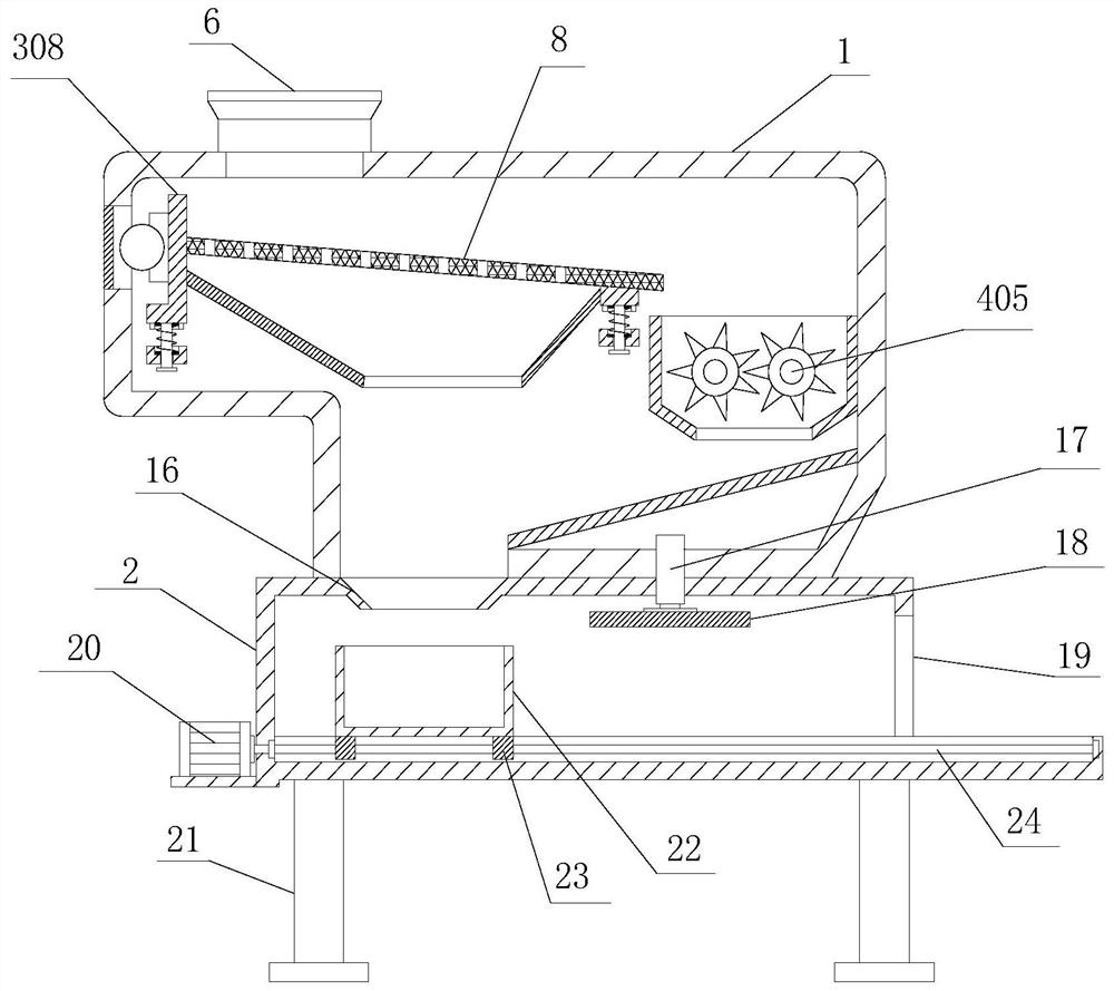
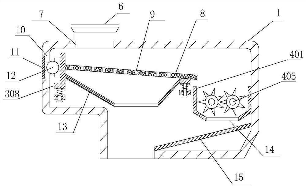
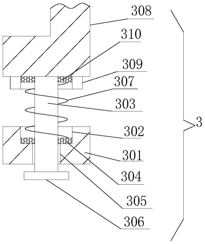
The invention relates to the technical field of metal material machining, and discloses a metal filing treatment device for metal material machining. The metal filing treatment device comprises a first machine body, a second machine body, a vibration mechanism and a crushing mechanism, wherein the second machine body is fixedly arranged at the bottom of the first machine body; the vibration mechanism is arranged in the first machine body; the crushing mechanism is arranged in the first machine body; and the vibration mechanism comprises a fixing plate, a first spring groove, an inserting column, an inserting hole and a vibration spring. According to the metal filing treatment device for metal material machining, the vibration device is started to drive a fixing frame to vibrate, a screening plate is driven to vibrate at a high speed, so that metal filing falling onto the screening plate is screened, the metal filing with the relatively small size continues to fall off, the metal filingwith the excessively large size enters a crushing groove, the metal filing with the small size is prevented from being crushed, and the phenomenon that the amount of the metal filing with the small-size is large and compression is inconvenient is avoided.

Description

technical field [0001] The invention relates to the technical field of metal material processing, in particular to a metal scrap processing device for metal material processing. Background technique [0002] With the development of the national economy, various fields are developing at a high speed, and many processing plants have sprung up. Metal product processing plants are particularly prosperous. With the expansion of metal processing plants, various large-scale metal processing equipment are in operation. However, the processing of metal products will inevitably cause a lot of metal waste, which will pollute the environment of the processing plant to a large extent, and seriously affect the processing efficiency of the processing plant and the production quality of metal products. Therefore, a large amount of metal The problem of metal waste disposal from product processing needs to be solved. Metal processing debris refers to the leftovers and debris generated during...

Claims


Application Information

Patent Timeline
IPC IPC(8): B30B9/32B02C18/14B02C18/24B02C23/16
CPCB30B9/327B02C18/0084B02C18/142B02C18/24B02C23/16B02C2023/165
Inventor 刘喜彬
Owner 恒凌金属制品(湖州)有限公司
Why Eureka
Try Eureka