
Production equipment for high-toughness polypropylene film

A polypropylene film and production equipment technology, applied in the field of tough polypropylene film production equipment, can solve the problems of uneven end faces on the left and right sides, and achieve the effect of ensuring the accuracy of the film width

Inactive Publication Date: 2021-04-02
腾娟
View PDF0 Cites 0 Cited by
  • Summary
  • Abstract
  • Description
  • Claims
  • Application Information

AI Technical Summary

Problems solved by technology

[0003] Based on the inventor's discovery above, the existing methods mainly have the following deficiencies, such as: when the equipment stretches the polypropylene raw material, the polypropylene raw material after the hot melt will be spread out in sheet form after being extruded. Open, but the left and right ends of the uncooled and shaped film tend to form irregular wavy contours with the stretching of the equipment, resulting in uneven left and right end faces when the film is rolled into a tube

Method used


Image

  • Production equipment for high-toughness polypropylene film
  • Production equipment for high-toughness polypropylene film
  • Production equipment for high-toughness polypropylene film

Examples


Embodiment 1

[0025] as attached figure 1 to attach Figure 5 Shown:

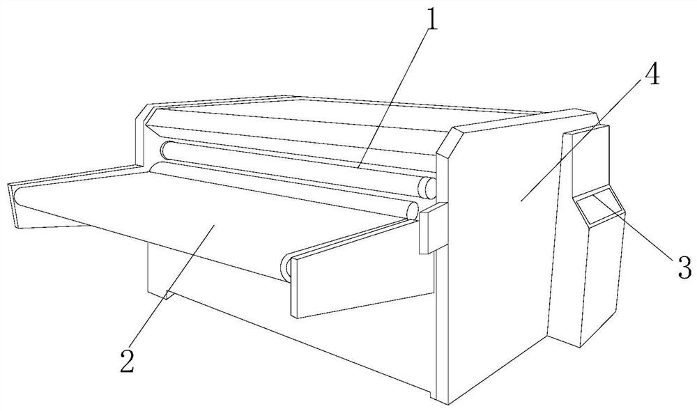
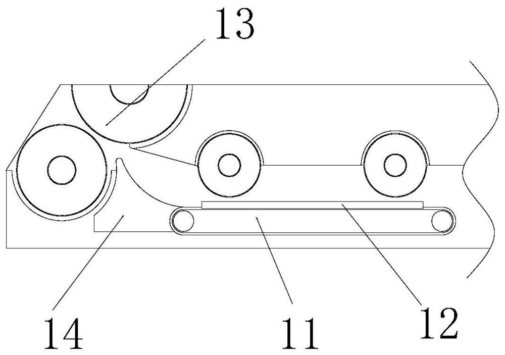
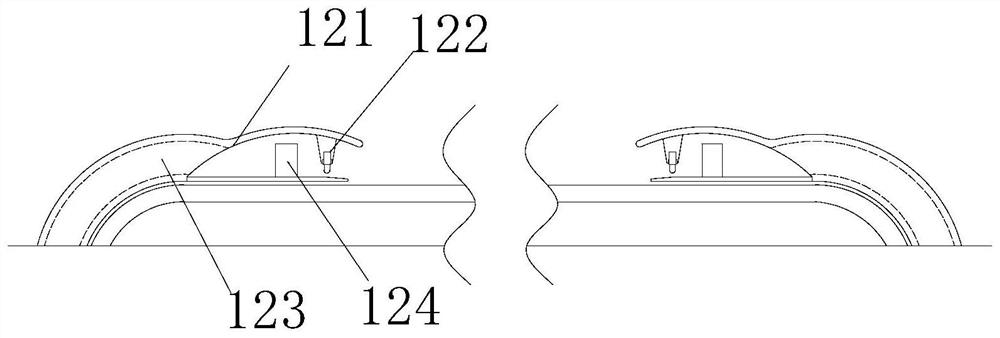
[0026] The present invention provides a kind of strong and tough polypropylene film production equipment, its structure comprises extruding mechanism 1, placing table 2, control panel 3, machine body 4, and described extruding mechanism 1 is inlayed on the top of machine body 4, and described placing The platform 2 is embedded and installed on the left end surface of the body 4, and the control panel 3 is installed on the outer side of the extrusion mechanism 1 by welding, and the outer end surface of the body 4 is attached to the control panel 3; the extrusion mechanism 1 It includes a transmission mechanism 11, a shaping mechanism 12, an extrusion wheel 13, and an arc block 14. The transmission mechanism 11 is embedded and installed on the right side of the arc block 14, and the shaping mechanism 12 is embedded so that it can be fitted on On the upper end surface of the transmission mechanism 11 , the extrusion wheel...

Embodiment 2

[0032] as attached Figure 5 to attach Figure 7 As shown: the transmission mechanism 11 includes a conveyor belt 111, a power wheel 112, and a cutting mechanism 113. The conveyor belt 111 is attached and wrapped on the outer end surface of the power wheel 112. The power wheel 112 is symmetrically installed on the upper and lower ends of the cutting mechanism 113. The cutting mechanism 113 is inlaid and connected to the conveyor belt 111, and the left and right sides of the outer contour of the conveyor belt 111 are provided with grooves inlaid with the cutting mechanism 113, which can effectively guide the protruding part of the film to be fixed.

[0033] Wherein, the cutting mechanism 113 includes a cutting wheel 131, an inlay groove 132, and a fitting wheel 133. The cutting wheel 131 is symmetrically installed on the left and right ends of the fitting wheel 133, and the inlay groove 132 is inlaid in the cutting mechanism. 113, the fitting wheel 133 fits and connects the ou...


PUM


Abstract

The invention discloses production equipment for a high-toughness polypropylene film. The production equipment for the high-toughness polypropylene film structurally comprises an extrusion mechanism,a containing table, a control panel and a machine body; the extrusion mechanism is arranged over the machine body in an inset mode; the containing table is embedded in the left side end face of the machine body; the control panel is installed below the outer side of the extrusion mechanism through welding; the control panel is connected to the outer side end face of the machine body in an attachedmode; due to the fact that a chip groove and a cutting block are arranged in a shaping mechanism, a film can be fixed through a second extrusion wheel in the film conveying process, the protruding part can be rubbed with the cutting block, a cutting blade and a protruding block are arranged in the cutting block, and while the protruding part is rubbed with the cutting block, the cutting blade cuts and stores the protruding film, so that the protruding film moves along the inner contour of a circulation hole and is discharged out into the chip groove, and the width accuracy of the film in thefilm production process is guaranteed.

Description

technical field [0001] The invention belongs to the field of polypropylene equipment, and more specifically relates to a production equipment of strong and tough polypropylene film. Background technique [0002] Polypropylene film production equipment is a kind of equipment that puts polypropylene raw materials in the equipment and uses the hot-melt equipment of the equipment to heat the raw materials, and then stretches and shapes the polypropylene material by applying pressure and pulling. [0003] Based on the inventor's discovery above, the existing methods mainly have the following deficiencies, such as: when the equipment stretches the polypropylene raw material, the polypropylene raw material after the hot melt will be spread out in sheet form after being extruded. Open, and the left and right ends of the uncooled and shaped film tend to form irregular wavy contours with the stretching of the equipment, resulting in uneven left and right end faces when the film is rol...

Claims


Application Information

Patent Timeline
IPC IPC(8): B29C55/02B29C37/02B29K23/00
CPCB29C37/02B29C55/005B29C55/02B29K2023/12
Inventor 腾娟
Owner 腾娟
Learn More