
Automatic double-sided chamfering device

A chamfering device, double-sided technology, applied in grinding drive devices, metal processing equipment, manufacturing tools, etc., can solve the problems of low processing efficiency, hidden dangers, time-consuming and labor-intensive safety, etc., and achieve the effect of improving chamfering efficiency.

Active Publication Date: 2021-04-02
赣州华京稀土新材料有限公司
View PDF5 Cites 4 Cited by
  • Summary
  • Abstract
  • Description
  • Claims
  • Application Information

AI Technical Summary

Problems solved by technology

[0003] The existing NdFeB production can process various shapes of NdFeB raw materials according to the demand during machining, such as the most commonly used cylindrical shape, hexahedron shape and tile shape, etc., and then process the processed raw materials Grinding and chamfering, while the existing cylindrical raw materials need to be chamfered on both sides, and the chamfering needs to be rough chamfered first and then finely chamfered, so it is necessary to perform rough chamfering on one side first, and then pass Turn the product over manually to perform rough chamfering on the other side. After the rough chamfering is completed, the product is manually taken out and put into another equipment to repeat the above chamfering process for fine chamfering, which leads to low processing efficiency and time-consuming manual operation. There are safety hazards in the laborious work, so now there is an urgent need for a device that can automatically complete the rough and fine chamfering of NdFeB

Method used


Image

  • Automatic double-sided chamfering device
  • Automatic double-sided chamfering device
  • Automatic double-sided chamfering device

Examples


Embodiment Construction

[0028] The technical solutions of the various embodiments of the present invention will be clearly and completely described below in conjunction with the accompanying drawings. Apparently, the described embodiments are only some of the embodiments of the present invention, not all of them. Based on the embodiments described in the present invention, all other embodiments obtained by persons of ordinary skill in the art without creative efforts are within the protection scope of the present invention.

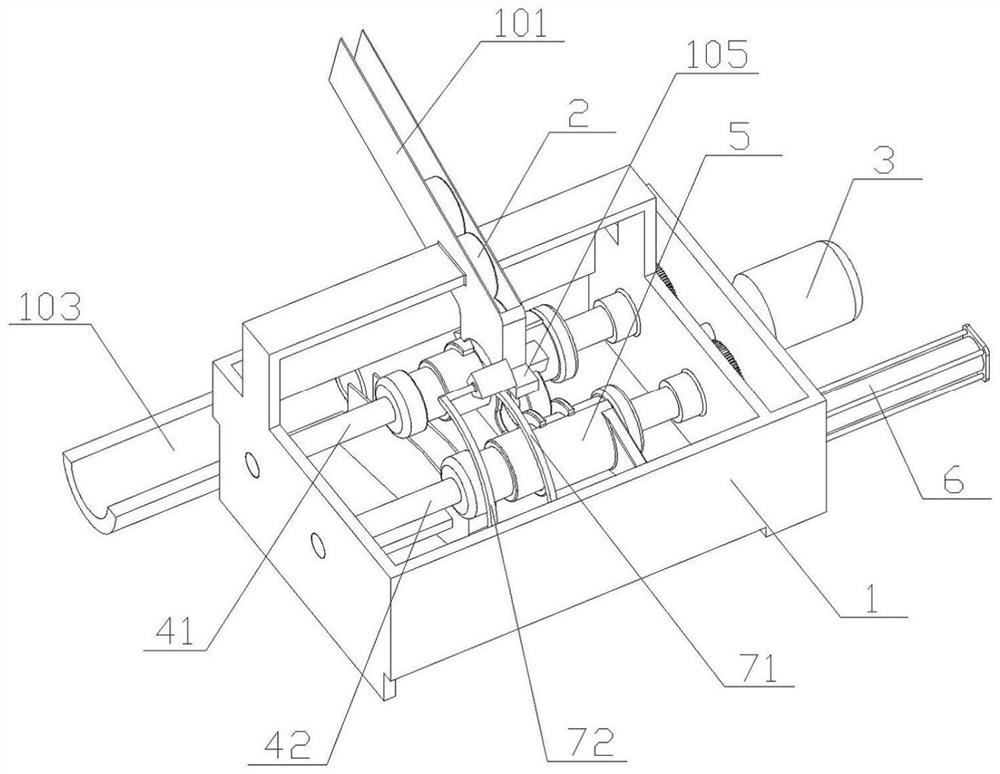
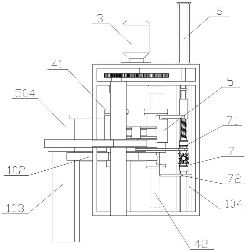
[0029] Example Figure 1 to Figure 8 As shown, an automatic double-sided chamfering device includes a box body 1, the upper part of the box body 1 is equipped with a feeding trough 101 for placing the NdFeB blank 2 to be chamfered, and the lower part is equipped with a feeding chute connected to the stacking tank 103 102, a motor 3 and a pushing component are installed on one side of the box body 1, a pair of drive rollers and a reversing mechanism are installed inside the box b...


PUM


Abstract

The invention discloses an automatic double-sided chamfering device which comprises a box body. A motor and a pushing part are further installed on one side of the box body, transmission rollers and areversing mechanism are installed in the box body, the transmission rollers are matched with the motor, a bearing seat is installed on the transmission rollers in a sliding mode, the bearing seat ismatched with a discharging groove and the pushing part, and the pushing part is further fixedly connected with the reversing mechanism. The reversing mechanism is matched with the bearing seat througha spring, and the reversing mechanism comprises a rough chamfering part, a fine chamfering part and a reversing motor. NdFeB blanks to be chamfered are driven by the transmission rollers to rotate together and are matched with a rough grinding head and a fine grinding head to be subjected to double-sided chamfering, so that the chamfering efficiency is improved. The rough chamfering part, the fine chamfering part and the reversing motor form the reversing mechanism, so that the rough chamfering process and the fine chamfering process can be completed simultaneously in one machining process. The feeding process, the rough chamfering process, the fine chamfering process, the discharging process and the stacking process of the device are all completed automatically, manual operation is not needed, efficiency is higher, and meanwhile safety is improved.

Description

technical field [0001] The invention relates to the field of NdFeB processing, in particular to an automatic double-sided chamfering device. Background technique [0002] NdFeB is a kind of permanent magnet material, which has the title of "Magnetic King". It is widely used in electronic products, such as hard disks, mobile phones, earphones and battery-powered tools. Sintering, machining, electroplating, magnetization and other processes. [0003] The existing NdFeB production can process various shapes of NdFeB raw materials according to the demand during machining, such as the most commonly used cylindrical shape, hexahedron shape and tile shape, etc., and then process the processed raw materials Grinding and chamfering, while the existing cylindrical raw materials need to be chamfered on both sides, and the chamfering needs to be rough chamfered first and then finely chamfered, so it is necessary to perform rough chamfering on one side first, and then pass Turn the pro...

Claims


Application Information

Patent Timeline
Patent Type & Authority Applications(China)
IPC IPC(8): B24B9/02B24B27/00B24B41/04B24B47/12B24B47/20B24B47/22
CPCB24B9/02B24B27/0076B24B41/04B24B47/12B24B47/22B24B47/20
Inventor 卢志强
Owner 赣州华京稀土新材料有限公司
Learn More