
Fire extinguishing system for inhibiting fire explosion of energy storage power station

A technology of fire extinguishing system and energy storage power station, which is applied in the field of fire extinguishing system, and can solve the problems that water cannot be vaporized quickly, cannot be cooled quickly, and the potential value of greenhouse effect is poor in fire extinguishing effect.

Inactive Publication Date: 2021-04-02
STATE GRID ELECTRIC POWER RES INST
View PDF6 Cites 4 Cited by
  • Summary
  • Abstract
  • Description
  • Claims
  • Application Information

AI Technical Summary

Problems solved by technology

This technology uses the combination of heptafluoropropane and fine water mist. However, there is still a lot of controversy about the use of fine water mist to extinguish electrical fires. Heptafluoropropane has the disadvantages of high greenhouse effect potential and poor fire extinguishing effect. In addition, the heat generated by the battery When out of control, the surface is in the low-temperature stage, and the water cannot be vaporized quickly, so it cannot cool down quickly
[0004] From the above, it can be seen that the fire protection system of the current energy storage power station has poor explosion suppression performance.

Method used


Image

  • Fire extinguishing system for inhibiting fire explosion of energy storage power station
  • Fire extinguishing system for inhibiting fire explosion of energy storage power station

Examples


Embodiment Construction

[0018] In order to make the purpose, technical solution and advantages of the present application clearer, the present application will be further described in detail below in conjunction with the accompanying drawings and embodiments. It should be understood that the specific embodiments described here are only used to explain the present application, and are not intended to limit the present application.

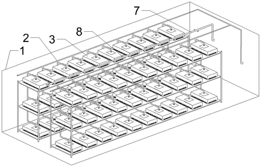
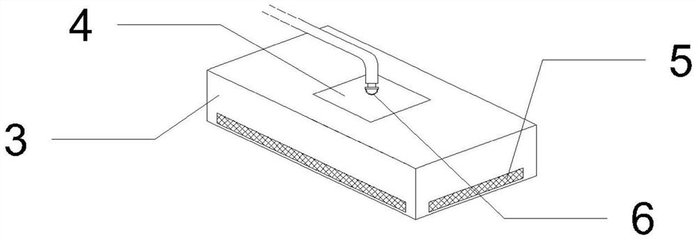
[0019] In one embodiment, such as figure 1 As shown, a fire extinguishing system for suppressing fire and explosion of an energy storage power station is provided, including: refrigerant cooling nozzle 6, refrigerant system pipe network 2, refrigerant storage tank filled with refrigerant, gas fire extinguishing system nozzle 8, gas fire extinguishing System pipe network 7 and the gas storage tank that gas fire extinguishing agent is housed;

[0020] The refrigerant cooling nozzle 6 is arranged above each battery module 3 inside the container energy storage power station 1...


PUM


Abstract

The invention relates to a fire extinguishing system for inhibiting fire explosion of an energy storage power station. The fire extinguishing system comprises a refrigerant cooling spray heads, refrigerant system pipe networks, refrigerant storage tanks filled with a refrigerant, gas fire extinguishing system spray heads, gas fire extinguishing system pipe networks and gas storage tanks filled with a gas fire extinguishing agent, wherein each refrigerant cooling spray head is arranged above each battery module in the container energy storage power station; each refrigerant cooling spray nozzleis connected to the refrigerant storage tank through the refrigerant system pipe network to form a fixed refrigerant pipe network system; the gas fire extinguishing system spray heads are arranged inthe container energy storage power station; each gas fire extinguishing system spray head is connected to the gas storage tank through the gas fire extinguishing system pipe network to form a fixed gas fire extinguishing agent pipe network system; a refrigerant is released through the fixed refrigerant pipe network systems to perform cooling and explosion suppression on the battery; and the fixedgas fire extinguishing agent pipe network systems release a gas extinguishing agent to extinguish flame, so that efficient fire extinguishing is achieved, and after-combustion and explosion are effectively inhibited.

Description

technical field [0001] The present application relates to the technical field of lithium-ion battery energy storage, in particular to a fire extinguishing system for suppressing fire and explosion in energy storage power stations. Background technique [0002] Energy storage power station technology is a sustainable and clean energy utilization technology. Energy storage not only ensures the stability and reliability of the grid system, but also an effective way to solve dynamic power quality problems such as voltage pulses, inrush currents, voltage dips, and instantaneous power interruptions. In recent years, energy storage has shown a good trend of diversified development, and energy storage technology has basically established the basis for industrialization in general. Energy storage is an emerging strategic industry. At present, the fire safety technology of energy storage power stations is one of the key bottlenecks hindering the large-scale development of energy stor...

Claims


Application Information

Patent Timeline
IPC IPC(8): A62C3/16A62C31/00A62C31/28H01M10/613H01M10/6568
CPCA62C3/16A62C31/005A62C31/28H01M10/613H01M10/6568A62C99/0018Y02E60/10
Inventor 陈光吴刘锁孙怡鞠振福徐亮李丽娜宿新红沈坤
Owner STATE GRID ELECTRIC POWER RES INST
Learn More