A new energy vehicle battery pack anti-collision auxiliary device

A technology for new energy vehicles and auxiliary devices, which is applied to battery pack components, electric vehicles, battery/battery traction, etc., which can solve the problems of battery heat release, electrolyte leakage, and low safety factor, so as to avoid excessive discharge thermal environment, reducing accidents, and stabilizing the power supply environment

Active Publication Date: 2022-08-09
GUILIN UNIV OF AEROSPACE TECH
View PDF2 Cites 0 Cited by
  • Summary
  • Abstract
  • Description
  • Claims
  • Application Information

AI Technical Summary

Problems solved by technology

[0004] The purpose of the present invention is: in order to solve the problem that the existing new energy vehicle battery pack anti-collision auxiliary device often uses the battery pack to move on the chassis, so that the counterweight is even and avoids the situation that the car is directly turned over, thereby protecting the battery from damage. Impact, to avoid explosion and fire, but the existing battery pack slides in a single direction on the chassis, and the battery pack is locked after sliding, making the battery pack unable to recover. If the battery pack is not controlled in time to return to the original fixed point, the car will still be in the chassis In the state of unbalanced counterweight, there will also be a danger of overturning during the subsequent driving process, and the existing new energy vehicle battery pack is protected by a metal shell. In fact, although the metal shell can withstand a part of the impact, if the metal shell The shell is broken, and the debris enters the battery pack, causing the electrolyte to leak out, and the battery is more dangerous due to a large amount of heat generation. Spontaneous combustion and explosion may occur, and the safety factor is low. A new energy vehicle battery pack anti-collision auxiliary device is provided.

Method used


Image

  • A new energy vehicle battery pack anti-collision auxiliary device
  • A new energy vehicle battery pack anti-collision auxiliary device
  • A new energy vehicle battery pack anti-collision auxiliary device

Examples


Embodiment Construction

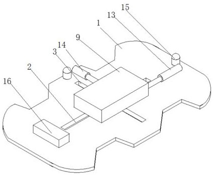
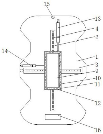
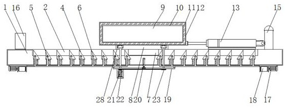
[0024] The technical solutions in the embodiments of the present invention will be clearly and completely described below with reference to the accompanying drawings in the embodiments of the present invention. Obviously, the described embodiments are only a part of the embodiments of the present invention, but not all of the embodiments. Based on the embodiments of the present invention, all other embodiments obtained by those of ordinary skill in the art without creative efforts shall fall within the protection scope of the present invention.

[0025] In the description of the present invention, it should be noted that the terms "center", "upper", "lower", "left", "right", "vertical", "horizontal", "inner", "outer", etc. The indicated orientation or positional relationship is based on the orientation or positional relationship shown in the accompanying drawings, which is only for the convenience of describing the present invention and simplifying the description, rather than ...


PUM


Abstract

The invention discloses an anti-collision auxiliary device for a new energy vehicle battery pack, which relates to the field of new energy vehicle batteries. A triangular block is arranged inside the longitudinal chute and the transverse chute, and the bottom end of the triangular block is connected with a spring. The invention realizes that the slider can slide in four directions at the top of the mounting plate, and judges which direction to push the slider according to the inclination information collected by the inclination sensor, so as to increase the counterweight of the automobile chassis, thereby reducing the probability of overturning, and achieving The purpose of protecting the battery, and after sliding, it is firstly locked by the triangular block with a special structure, and the slider cannot return to the original point until the driver judges that there is no danger of overturning, and controls the first motor, the first electric push rod and The second electric push rod is activated, and pushes the slider together with the battery case to the origin, which ensures smooth subsequent formation.

Description

technical field [0001] The invention relates to the field of new energy vehicle batteries, in particular to a new energy vehicle battery pack anti-collision auxiliary device. Background technique [0002] New energy vehicles refer to the use of unconventional vehicle fuels as the power source (or the use of conventional vehicle fuels, the use of new vehicle power units), and the integration of advanced technologies in vehicle power control and drive. Vehicles with new technology and new structure, and new energy vehicles include pure electric vehicles, extended-range electric vehicles, hybrid electric vehicles, fuel cell electric vehicles, hydrogen engine vehicles, etc. [0003] Existing new energy vehicle battery pack anti-collision auxiliary devices often use the way that the battery pack moves on the chassis, so that the counterweight is evenly distributed to avoid the situation that the car directly rolls over, thereby protecting the battery from impact, avoiding explosi...

Claims


Application Information

Patent Timeline
Patent Type & Authority Patents(China)
IPC IPC(8): H01M50/242H01M50/204H01M50/244H01M50/249B60L50/64
CPCB60L50/64Y02T10/70
Inventor 唐学帮陈元华
Owner GUILIN UNIV OF AEROSPACE TECH
Why Eureka
Try Eureka