
Projection lens and laser projection equipment

A projection lens and laser beam technology, applied in optics, optical components, instruments, etc., can solve the problem of high complexity of projection size

Active Publication Date: 2021-03-30
QINGDAO HISENSE LASER DISPLAY CO LTD
View PDF5 Cites 0 Cited by
  • Summary
  • Abstract
  • Description
  • Claims
  • Application Information

AI Technical Summary

Problems solved by technology

The problem of high complexity of adjusting the projection size of the projection lens in the related art can be solved, and the technical solution is as follows:

Method used


Image

  • Projection lens and laser projection equipment
  • Projection lens and laser projection equipment
  • Projection lens and laser projection equipment

Examples


Embodiment Construction

[0041] In order to make the objects, technical solutions, and advantages of the present invention, the embodiments of the present invention will be further described in detail below with reference to the accompanying drawings.

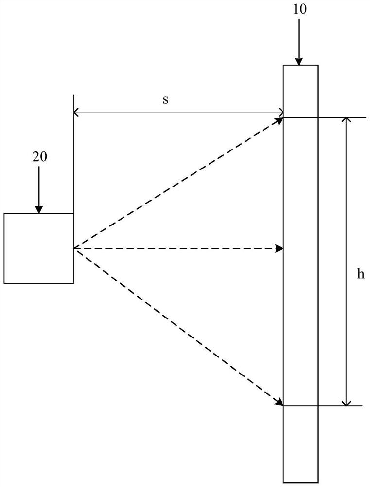
[0042] figure 1 It is a schematic diagram of the implementation environment according to the embodiment of the present invention, which may include screen 10 and projection lens 20.

[0043] The projection lens 20 can transmit the image beam to the screen 10, which can form an image on the screen 10. The current trend is to reduce the projection ratio of the projection lens 20 (the projection ratio is the ratio of the projection distance S and the picture width H, the projection distance S is the distance between the projection lens 20 and the screen 10), the smaller the projection ratio, the projection lens The larger image can be projected on the shorter projection distance. The projection lens of the transmissive is a projection lens that can be calle...


PUM


Abstract

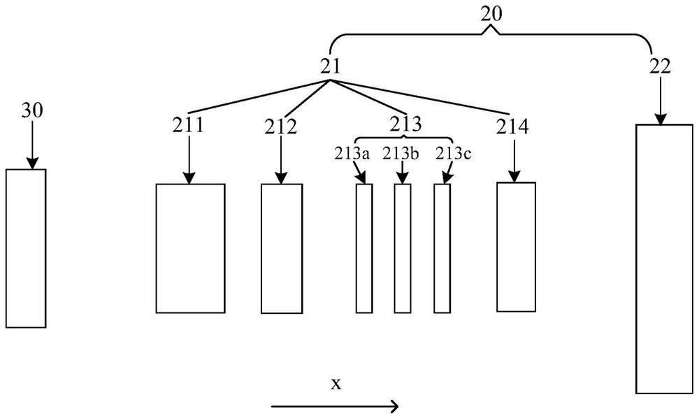
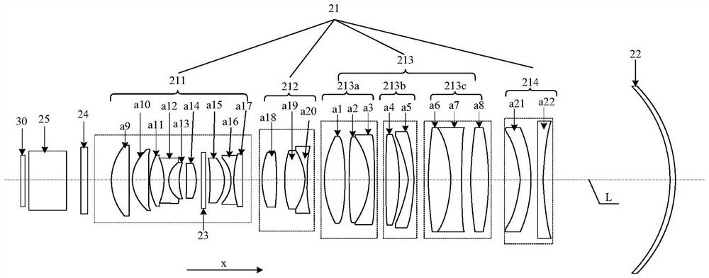
The invention discloses a projection lens and laser projection equipment, and belongs to the field of optical equipment. The projection lens comprises a refractor group and a reflector. The refractorgroup comprises a first lens group, a second lens group, a third lens group and a fourth lens group. The third lens group comprises at least one sub-lens group, each sub-lens group can move along thelight emitting direction or the reverse direction of the light emitting direction, the projection size of the projection lens can be adjusted, and the adjustment of the projection size of the projection lens is effectively simplified.

Description

Technical field [0001] The present invention relates to the field of optical devices, and in particular, to a projection lens and a laser projection device. Background technique [0002] With the improvement of science and technology, projection lenses are increasingly widely used in people's work and life, such as education, office, household or entertainment, for example, for projection lenses used in home theater, the higher the resolution of projected lens, users The higher the viewing experience. Therefore, people's requirements for projected lenses are getting higher and higher. [0003] In the relevant technique, household projection devices tend to use ultra-suction laser projection devices, which include: light valve and projection lens. The projection lens includes: a refractive protector group and a mirror. Among them, the light valve is used to generate an image beam, and the image beam first enters the reflection mirror group, and the refractive mirror sets the image...

Claims


Application Information

Patent Timeline
IPC IPC(8): G03B21/14G03B21/20G02B13/00
CPCG03B21/142G03B21/2033G02B13/0045G02B13/006
Inventor 李晓平
Owner QINGDAO HISENSE LASER DISPLAY CO LTD
Learn More