Equipment for processing hydraulic brake systems of vehicles
A technology of hydraulic braking and equipment, applied in the direction of fluid pressure actuation system components, mechanical equipment, fluid pressure actuation devices, etc., can solve the problems of single function, incomplete equipment, low utilization rate, etc.
- Summary
- Abstract
- Description
- Claims
- Application Information
AI Technical Summary
Problems solved by technology
Method used
Image
Examples
Embodiment 1
[0123] like Figure 4-Figure 8As shown, the equipment 100 may include: equipment oil tank 11, main pipeline 21, flushing exhaust pipeline 31, external refueling pipeline 41, internal refueling pipeline 51, switching pipeline 61, detection pipeline 71, external oil inlet pipeline 27. The oil discharge pipeline 28 is connected externally. The main pipeline 21 includes: an oil inlet pipeline section 211 , a preset pipeline section 212 and a detection pipeline section 213 arranged in sequence along the oil flow direction. A first upstream filter 2411 and a second upstream filter 2412 are provided between the oil inlet pipeline section 211 and the preset pipeline section 212, a pressure gauge 25 is provided between the preset pipeline section 212 and the detection pipeline section 213, and the detection pipeline section 213 A downstream filter 242 is provided downstream of . The equipment oil tank 11 has a temperature sensor 13 , an air filter 12 , a liquid level gauge 14 and a s...
Embodiment 2
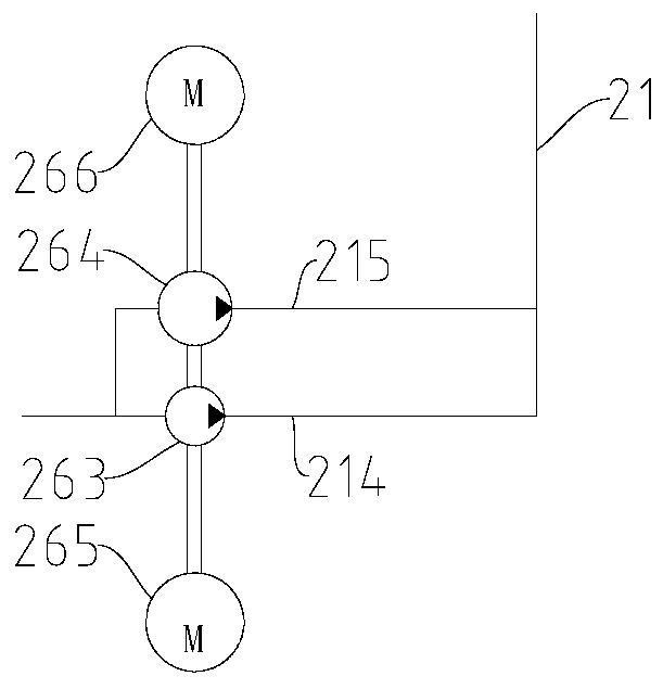
[0144] like Figure 9-Figure 13 As shown, compared with the first embodiment above, the second embodiment has the same general structure, and the same components use the same reference numerals. The differences mainly include: (1) The oil pump device 26 includes an oil pump 261 and an electric motor 262. Then there is a double pump, so that the external oil inlet pipeline 27 connected in parallel with the oil inlet pipeline section 211, and the external oil discharge pipeline 28 and the control device 29 related to the external oil inlet pipeline 27 can be omitted. (2) The switch device 62 is a manually adjusted direction control cock, and the switch device 53 and the second oil suction filter 52 are canceled on the internal fuel oil pipeline 51 . (3) The first oil suction filter 63 on the switch line 61 is eliminated, and the third oil suction filter 216 is provided between the inlet port 21 a of the main line 21 and the oil pump 261 . In contrast, the structure of the secon...
Embodiment 3
[0161] like Figure 14-Figure 18 As shown, compared with the above-mentioned embodiment 2, the third embodiment has the same general structure, and the same components use the same reference numerals. The differences mainly include: (1) the inlet port 21a and the oil pump 261 arranged on the main pipeline 21 are omitted Between the third oil suction filter 216. (2) There is only one upstream filter 241 . (3) The external refueling pipeline 41 is canceled, and the flushing exhaust pipeline 31 is a multifunctional pipeline 31A that can be installed with a refueling gun 34, so that the multifunctional pipeline 31A can be used for flushing, exhaust, and refueling of the vehicle hydraulic braking system . (4) Cancel the first overflow valve 43, set the second overflow valve 44 on the multifunctional pipeline 31A, set the third overflow valve 45 on the preset pipeline section 212, and set the preset position on the main pipeline 21 One-way valve 217 upstream of line section 212 ....
PUM
 Abstract
Description
Claims
Application Information
 - R&D
- Intellectual Property
- Life Sciences
- Materials
- Tech Scout
- Unparalleled Data Quality
- Higher Quality Content
- 60% Fewer Hallucinations
Browse by: Latest US Patents, China's latest patents, Technical Efficacy Thesaurus, Application Domain, Technology Topic, Popular Technical Reports.
© 2025 PatSnap. All rights reserved.Legal|Privacy policy|Modern Slavery Act Transparency Statement|Sitemap|About US| Contact US: help@patsnap.com


