Target area avoidance relative pose integrated control method considering rectangular field of view

A technology of relative pose and target area, which is applied in the direction of spaceflight equipment, spaceflight vehicles, spaceflight vehicle guidance devices, etc., and can solve the problems of small maneuverable space and large constraint range

Active Publication Date: 2021-03-30
HARBIN INST OF TECH
View PDF13 Cites 2 Cited by
  • Summary
  • Abstract
  • Description
  • Claims
  • Application Information

AI Technical Summary

Problems solved by technology

[0006] The invention considers the rectangular field of view of the sensor of the spacecraft, solves the problem that the constraint range of the system state is relatively large, resulting in a small feasible space for maneuvering, and at the same time realizes the optimization of the control of the spacecraft

Method used


Image

  • Target area avoidance relative pose integrated control method considering rectangular field of view
  • Target area avoidance relative pose integrated control method considering rectangular field of view
  • Target area avoidance relative pose integrated control method considering rectangular field of view

Examples


specific Embodiment approach 1

[0097] Specific implementation mode one: the target area considering the rectangular field of view described in this implementation mode avoids the relative pose integration control method, which includes:

[0098] Step 1: Establish a relative pose integration model;

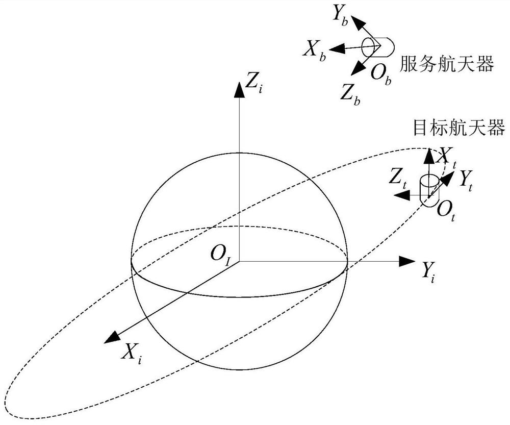
[0099] (1) Define the relevant coordinate system as the basis for model establishment, such as figure 2 shown;

[0100] a) Define the geocentric inertial coordinate system O i x i Y i Z i ;

[0101] The geocentric inertial coordinate system is expressed as O i x i Y i Z i , where O i is the center of mass of the earth, O i x i Axis by O i Pointing to the intersection of the flat ecliptic and flat equator at epoch J2000.0, O i Z i Axis perpendicular to the epoch J2000.0 flat equator and pointing toward the North Pole, O i x i Y i Z i into a right-handed coordinate system.

[0102] b) Define the service spacecraft body coordinate system O b x b Y b Z b ;

[0103] The body coordinate syste...

specific Embodiment approach 2

[0218] Embodiment 2: This embodiment differs from Embodiment 1 in that this embodiment describes that the artificial potential function has a unique minimum value, that is, the potential function is a convex potential function. Prove that the total potential function is convex by proving that each term in the potential function is convex. For the convenience of proof, the "vector" notation of dual quaternions is introduced, namely:

[0219]

[0220] (1) Attractive potential function;

[0221] First prove that the attractive potential function is a convex function, and obtain the attractive potential function pair The first-order and second-order partial derivatives of are:

[0222]

[0223] ▽ 2 V a =2k a A T A>0 (72) where A is and The transformation matrix between, that is

[0224] The second-order partial derivative of the attractive potential function is greater than 0, indicating that the attractive potential function is a convex function.

[0225] (2)...


PUM


Abstract

The invention discloses a target area avoidance relative pose integrated control method considering a rectangular field of view, and relates to the field of spacecraft on-orbit service. In order to solve the problem of small feasible space of maneuvering and realize optimization of spacecraft control, a view field real model is constructed to the greatest extent by considering an actual rectangular pyramid view field of a spacecraft sensor, a relative pose integrated kinematics model is established, and two constraints of a constraint pose and a forbidden area are constructed, an attraction potential function and a repulsion potential function are designed respectively, so that the system state meets the constraint attitude in the whole approximation maneuvering process, and regional constraint is forbidden; and a pose integrated control law is designed to realize continuous observation of the target spacecraft and avoidance of detection of the target spacecraft while a service spacecraft can reach an expected position in the process of approaching the target spacecraft. The method is suitable for on-orbit observation and avoidance of spacecrafts.

Description

technical field [0001] The invention relates to an integrated control method for avoiding a relative pose of a target area considering a rectangular field of view in a spacecraft. The invention belongs to the field of space on-orbit service technology. Background technique [0002] With the vigorous development of aerospace technology, tens of thousands of spacecraft of various shapes have been launched into space. In order to make more efficient and reasonable use of the space environment and occupy space resources effectively and quickly, the level of on-orbit services and space attack and defense in various countries is increasing day by day. . As a key part of space missions such as on-orbit service and debris removal, the stage of the service spacecraft approaching the target spacecraft has received extensive attention and research. In view of the multi-constraint requirements such as the visibility of the target spacecraft and avoiding the sight area of ​​the target s...

Claims


Application Information

Patent Timeline
Patent Type & Authority Applications(China)
IPC IPC(8): B64G1/24
CPCB64G1/244B64G1/245
Inventor 郭延宁王靓玥马广富吕跃勇
Owner HARBIN INST OF TECH
Why Eureka
Try Eureka