Mine curve car pusher

A technology of carts and curves, which is applied in the direction of mechanical equipment, engine components, railway car body parts, etc., and can solve the problems of shortened service life of carts, inability of carts to work, and lack of protection and maintenance of carts Measures and other issues to achieve the effect of increasing the moving speed and convenient and efficient adjustment

Inactive Publication Date: 2021-03-30
枣庄山科矿山设备有限公司
View PDF8 Cites 0 Cited by
  • Summary
  • Abstract
  • Description
  • Claims
  • Application Information

AI Technical Summary

Problems solved by technology

[0003] However, most of the existing trolley machines can only move along the straight track, and cannot carry out the cart operation in the curve. However, in the actual working environment, due to the influence of various environmental factors, there are often curves in the track line. The existing carts cannot conveniently carry out cart operations in curves, and the existing carts lack corresponding protection and maintenance measures, which will easily shorten the service life of the carts

Method used


Image

  • Mine curve car pusher
  • Mine curve car pusher
  • Mine curve car pusher

Examples


Embodiment 1

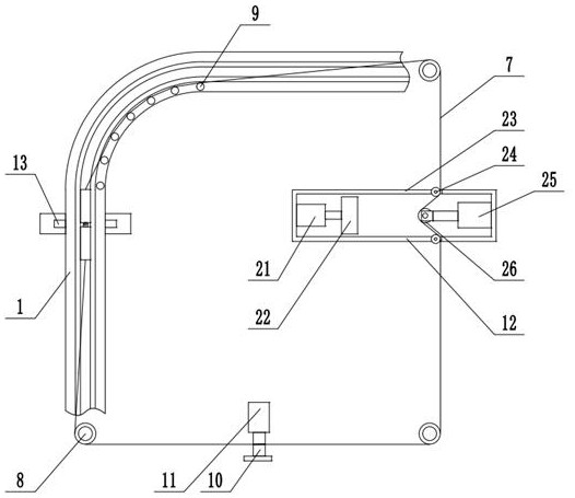
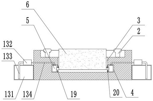
[0023] see Figure 1-3 , mine curve cart machine, including a slideway 1 with a curve, two sets of guide rails 2 are fixedly installed in the slideway 1, and a trolley groove 3 is opened on the slideway 1 between the two sets of guide rails 2, and the pusher The left and right inner walls of the car groove 3 are respectively provided with rolling grooves 4 in the slideway 1. The cart body 6 is placed in the cart groove 3. The bottom of the body 6 is rotated around and installed with a roller 5 located in the rolling groove 4. The curved part There are multiple sets of guide shafts 9 distributed at equal intervals on the top of the slideway 1, multiple sets of turning rollers 8 are installed on the foundation outside the slideway 1, and the front and rear ends of the body 6 are fixedly connected with the guide shafts 9 and the turning rollers 8. The closed steel rope 7 is slidably connected. The transmission drum 10 is slidably connected to the steel rope 7. The transmission dr...

Embodiment 2

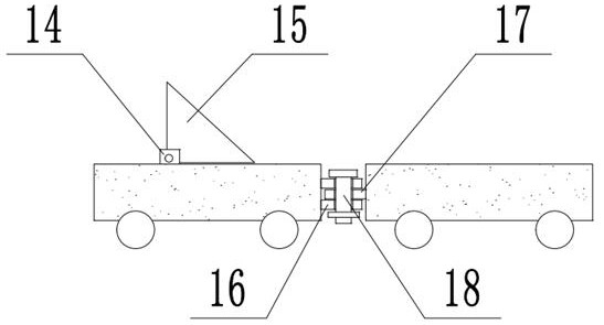
[0025] On the basis of Embodiment 1, a connection plate 16 and a clamping plate 17 are fixedly installed on the opposite side walls of the left and right groups of bodies 6, respectively, and the connecting plate 16 and the clamping plate 17 are respectively provided with through holes. The fixed pin shaft 18 is detachably installed with the clamping plate 17 through the through hole, and the left and right two groups of bodies 6 can be rotated and connected through the fixed pin shaft 18 to facilitate movement on the curved part of the slideway 1. The lubricating part 13 includes a fixed On the fuel tank 131 on the left and right sides of the slideway 1, a pump 132 is fixedly installed on the top of the fuel tank 131. The pump 132 is connected with an oil guide pipe 133 leading to the inside of the fuel tank 131. The pump 132 is connected with a rolling groove 4 extending to the slideway 1. The oil delivery pipe 134 inside pumps the lubricating oil in the oil tank 131 into the...


PUM


Abstract

The invention belongs to the technical field of car pusher equipment, discloses a mine curve car pusher, and solves the problem that an existing car pusher lacks corresponding protection and maintenance measures. According to the technical scheme, the car pusher comprises a slideway with a bend, a car pushing groove is formed in the slideway, rolling grooves are formed in the left inner wall and the right inner wall of the car pushing groove towards the interior of the slideway, the car pusher body is placed in the car pushing groove, rolling wheels located in the rolling grooves are rotationally installed on the periphery of the bottom of the body, a plurality of sets of guide shafts distributed at equal intervals are installed at the top of the slideway of the bend, a plurality of sets of steering rollers are installed on the foundation outside the slideway, steel ropes are fixedly connected with the front end and the rear end of the body, transmission rollers are slidably connectedwith the steel ropes, hydraulic motors are connected with the transmission rollers, tightening components are connected with the steel ropes, a front mounting plate and a rear mounting plate are fixedly mounted at the top of the body, a triangular push claw is rotatably connected between the front mounting plate and the rear mounting plate through a rotating shaft, and lubricating components are mounted on the left and right sides of the slideway.

Description

technical field [0001] The invention relates to the technical field of trolley equipment, in particular to a mine curve trolley. Background technique [0002] Industrial and mining enterprises usually use quasi-gauge or narrow-gauge railways to transport coal, ore, building materials and other materials. Long-distance trains or mine cars generally need to be pulled by locomotives. Rope carts or manual carts can be used to move the vehicle. The endless rope cart arranges the traction wire rope in the middle of the track and connects it with the cart in the middle of the track. The cart moves back and forth along the track to realize the cart. Operation. [0003] However, most of the existing trolley machines can only move along the straight track, and cannot carry out the cart operation in the curve. However, in the actual working environment, due to the influence of various environmental factors, there are often curves in the track line. The existing pusher cannot convenie...

Claims


Application Information

Patent Timeline
IPC IPC(8): B61J3/00B61J3/04F16N7/38F16N7/30F16N21/00
CPCB61J3/00B61J3/04F16N7/38F16N7/30F16N21/00
Inventor 刘世春熊健龙苗艳春褚福星杜善营王炳伟
Owner 枣庄山科矿山设备有限公司
Why Eureka
Try Eureka