Protection device for roof photovoltaic power station assembly plug connector

A photovoltaic power station and protection device technology, applied in photovoltaic power generation, photovoltaic modules, electrical components, etc., can solve problems such as poor stability of photovoltaic power generation, reduced wiring life, broken wires, etc., to achieve overall convenience for installation, reduce maintenance costs, and facilitate The effect of ventilation

Pending Publication Date: 2021-03-26
湖南安华源电力科技有限公司
View PDF0 Cites 0 Cited by
  • Summary
  • Abstract
  • Description
  • Claims
  • Application Information

AI Technical Summary

Problems solved by technology

By 2009, China's grid-connected power generation had not yet started to be fully promoted. On December 4, 2013, the world's largest hydro-solar hybrid photovoltaic power station - Longyangxia hydro-solar hybrid 320 MW located in the photovoltaic power generation park of Gonghe County, Qinghai Province The grid-connected photovoltaic power station has officially started grid-connected operation. Using water and solar power to generate electricity, the problem of poor stability of photovoltaic power generation has been solved from the power source. The photovoltaic panels laid on the roof are composed of photovoltaic panels one by one. There will be a wire at the bottom, and this wire will be connected to a branch of a bus to uniformly transmit electric energy to the power storage device. The factors in the wiring will greatly reduce the life of the wiring, and the external force will cause the interconnected wire ends to break, causing losses

Method used


Image

  • Protection device for roof photovoltaic power station assembly plug connector
  • Protection device for roof photovoltaic power station assembly plug connector
  • Protection device for roof photovoltaic power station assembly plug connector

Examples


Embodiment Construction

[0020] The following will clearly and completely describe the technical solutions in the embodiments of the present invention with reference to the accompanying drawings in the embodiments of the present invention. Obviously, the described embodiments are only some, not all, embodiments of the present invention.

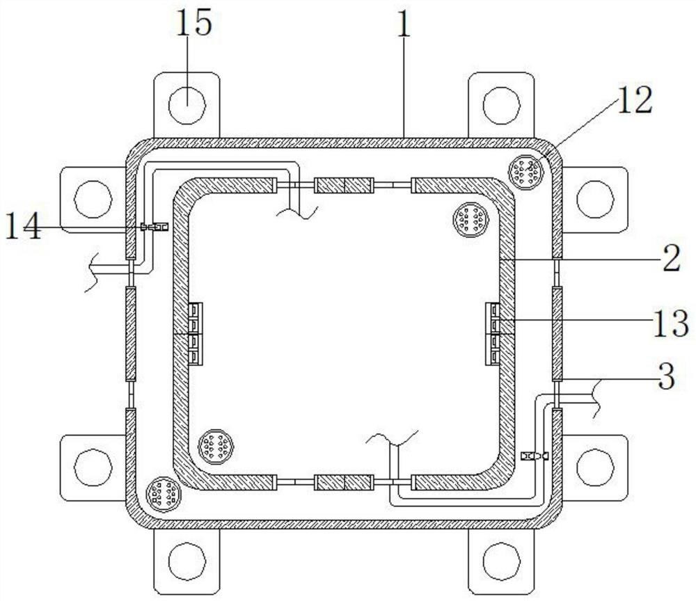
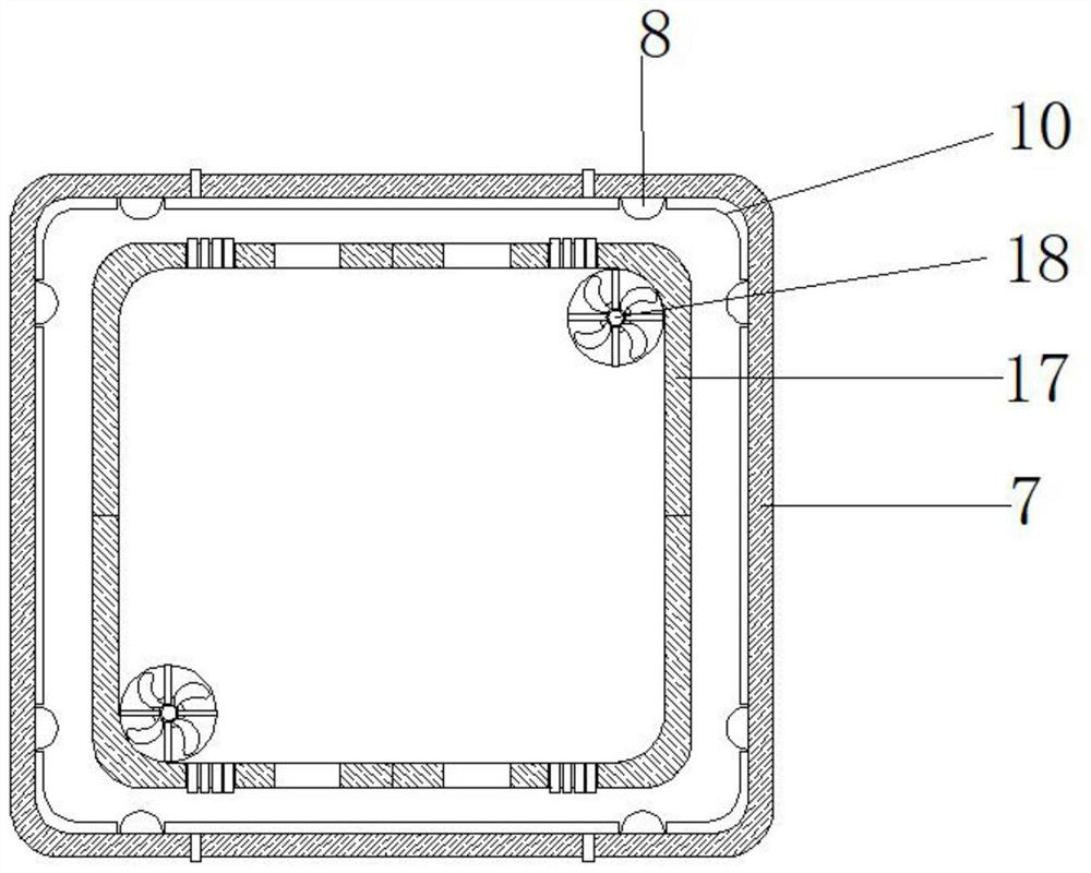
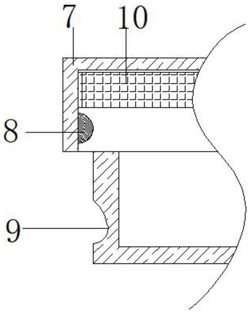
[0021] refer to Figure 1-5 , a protection device for roof photovoltaic power station component connectors, including a box body 1, the top of the box body 1 is not sealed, a square enclosure 2 is welded at the center of the bottom inner wall of the box body 1, and the box body 1 Both sides of the body 1 are provided with wiring holes 3, and the inner wall of the wiring hole 3 is sleeved with a rubber ring 4, and the rubber ring 4 is composed of a ring 5 and four fan-shaped rubber sheets 6, and the four pieces The fan-shaped rubber sheet 6 is bonded to the inner wall of the ring 5, the top of the box body 1 is clamped with a cover 7, and the inner walls of both sides...


PUM


Abstract

The invention discloses a protection device for a roof photovoltaic power station assembly plug connector. The protection device comprises a box body, wherein the top part of the box body is not sealed, a square fence is welded to the center of the inner wall of the bottom part of the box body, wiring holes are formed in the two sides of the box body, a clamping cover is clamped to the top part ofthe box body, protrusions are welded to the inner walls of the four sides of the clamping cover, grooves matched with the protrusions are formed in the outer walls of the four sides of the box body,a visible plate is installed in the center of the clamping cover, and drying boxes are installed at the corners of the two sides of the inner wall of the bottom part of the box body and the corners ofthe two sides of the interior of the square fence. Through adopting the box body, the clamping cover, a mounting block, an auxiliary handle and the wiring holes, the box body is in threaded connection with the back of a photovoltaic panel through the mounting block, two kinds of wires enter the square enclosure from the wiring hole of the box body around 1 / 4 circle, then the clamping cover is clamped through the auxiliary handle, and compared with a traditional mode, overall mounting is more convenient, connector joints are structured, the connector joints are protected, and the service lifeof connectors is prolonged.

Description

technical field [0001] The invention relates to the technical field of roof photovoltaic power plants, in particular to a protection device for component connectors of roof photovoltaic power plants. Background technique [0002] Photovoltaic power station refers to a photovoltaic power generation system that uses solar energy and uses special materials such as crystalline silicon panels, inverters and other electronic components to connect to the grid and transmit power to the grid. Photovoltaic power plants are green power development energy projects that are encouraged by the state. It can be divided into independent power generation system with battery and grid-connected power generation system without battery. Solar power generation is divided into photothermal power generation and photovoltaic power generation. The commercialization of solar power in the current period refers to solar photovoltaic power generation. Photovoltaic power generation products are mainly u...

Claims


Application Information

Patent Timeline
Patent Type & Authority Applications(China)
IPC IPC(8): H02S40/34
CPCH02S40/34Y02B10/10Y02E10/50
Inventor 李宁良周世大肖慧明
Owner 湖南安华源电力科技有限公司
Why Eureka
Try Eureka