


Quick Research
Generate reliable direction feasibility study reports for your R&D in just a few steps.

Technical Q&A
Discover and master advanced knowledge NOW. Basics, ideas, possibilities, all at once.

Find Solutions
As an expert in R&D theories, this can generate solutions to your technical problems instantly.

Evaluate Feasibility
Analyze your overall solution with one click, know your potential R&D risks in advance.

Monitor Landscape
Get weekly tech updates, stay abreast of the latest tech innovations and key insights.
Novel permanent magnet motor capable of dissipating heat
A permanent magnet motor, heat dissipation technology, applied in the direction of electrical components, electromechanical devices, electric components, etc., can solve the problems of practical performance enhancement
- Summary
- Abstract
- Description
- Claims
- Application Information
AI Technical Summary
Problems solved by technology
Method used
Image

Examples
Embodiment 1
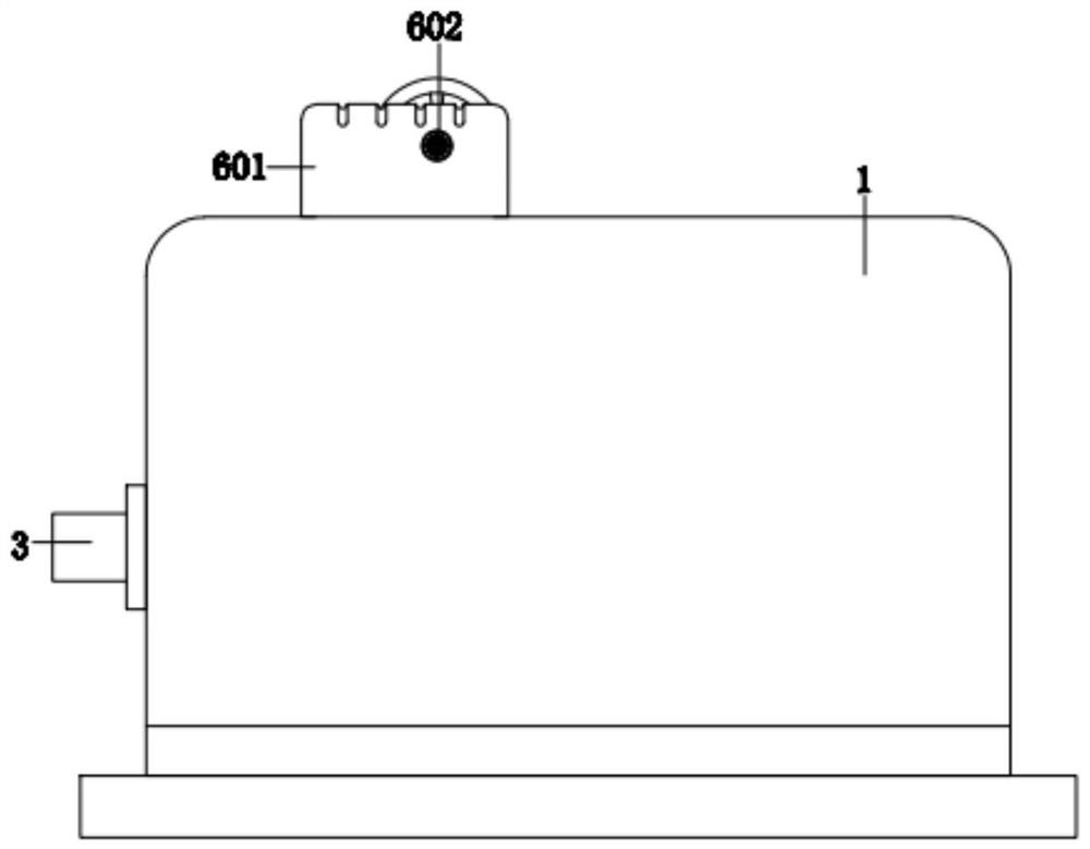
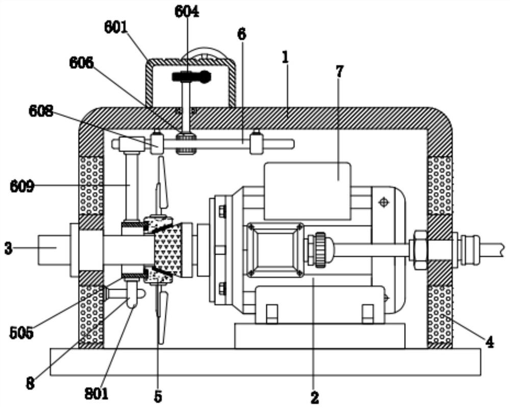
[0033] A new type of heat-dissipating permanent magnet motor, including a chassis 1, a permanent magnet motor body 2 is arranged on the right side of the interior of the chassis 1, the permanent magnet motor body 2 is fixedly connected to the inner bottom of the chassis 1 through a mounting bracket, and the permanent magnet motor body The left side of 2 is provided with rotating shaft 3, and rotating shaft 3 is fixedly connected with the output shaft of permanent magnet motor body 2, and rotating shaft 3 is connected with casing 1 through ball bearing rotation, and the left and right sides of casing 1 are provided with a plurality of through holes 4, and rotating shaft 3 The right side of the outer wall is provided with a heat dissipation mechanism 5, the heat dissipation mechanism 5 includes a conical cylinder 501, a groove block 502, a rubber cylinder 503, fan blades 504 and a cylinder 505, the conical cylinder 501 is sleeved on the right side of the outer wall of the rotating...
Embodiment 2
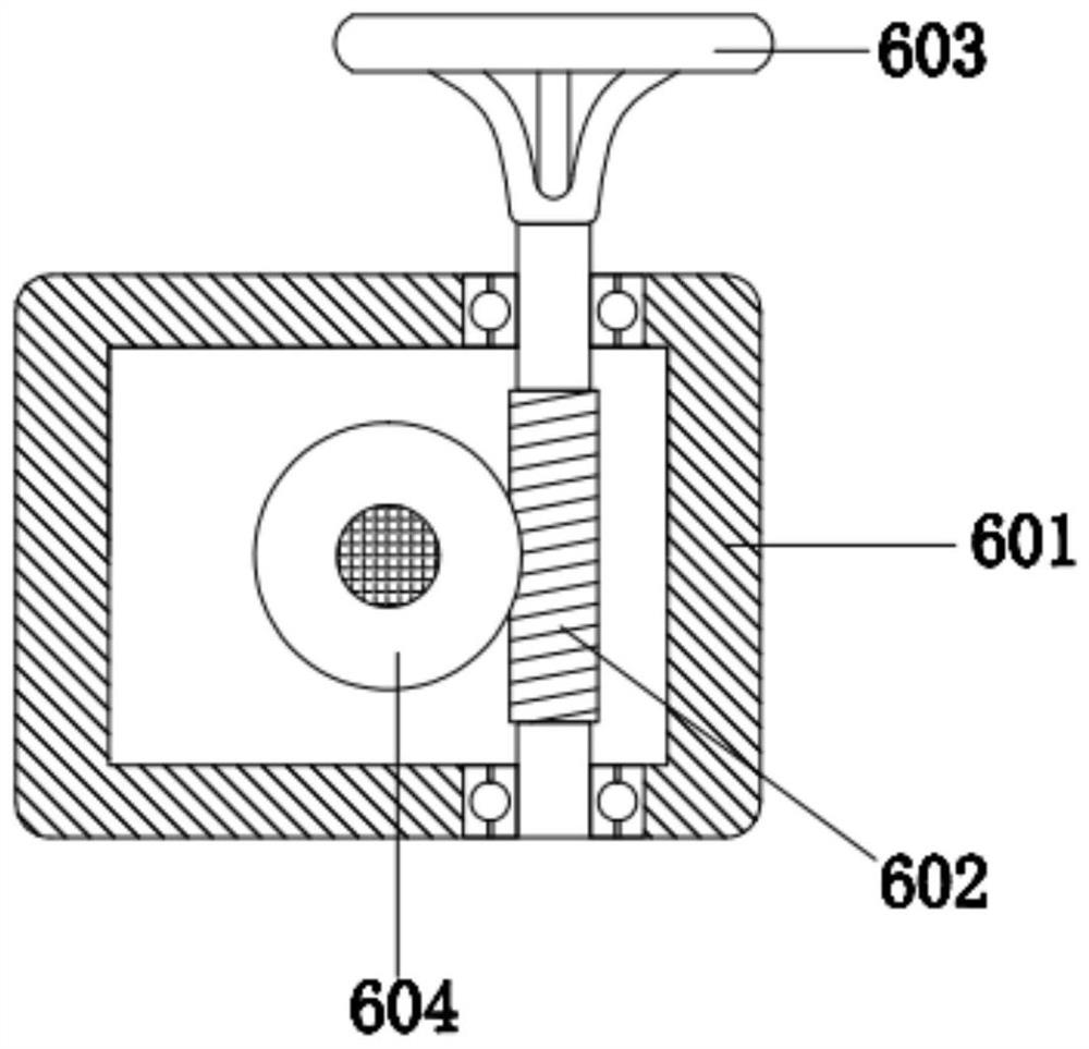
[0035] As an option, see figure 1 , 2, 3 and 6, a new type of heat-dissipating permanent magnet motor, a transmission mechanism 6 is arranged above the inside of the cabinet 1, and the transmission mechanism 6 includes a casing 601, a worm 602, a knob 603, a worm wheel 604, a vertical rod 605, a tooth column 606, A rack 607, a sleeve 608 and a vertical bar 609, the casing 601 is located on the left side of the upper surface of the chassis 1, the bottom of the casing 601 is fixedly connected with the upper surface of the casing 1, and the inside of the casing 601 is provided with a worm 602, The worm 602 is rotationally connected with the chassis 1 through a ball bearing. The rear end of the worm 602 is provided with a knob 603. The knob 603 is fixedly connected with the contact surface of the worm 602. The left side of the outer wall of the worm 602 is meshed with a worm wheel 604, and the inner wall of the worm wheel 604 A vertical rod 605 is provided, and the outer wall of ...
Embodiment 3
[0038] As an option, see figure 2 , a new type of heat-dissipating permanent magnet motor, an efficiency raising mechanism 7 is arranged above the outer wall of the permanent magnet motor body 2, and the efficiency raising mechanism 7 includes an arc-shaped plate 701, a groove 702 and a round hole 703, and the arc-shaped plate 701 is located in the permanent magnet motor Above the outer wall of the body 2, the main material of the arc-shaped plate 701 is copper, and the lower surface of the arc-shaped plate 701 is provided with a plurality of grooves 702, and the lower surface of the arc-shaped plate 701 is in contact with the outer wall of the permanent magnet motor body 2. Fixedly connected, the front surface of the arc-shaped plate 701 is provided with a plurality of round holes 703;
[0039] The solution in this embodiment can be selectively used in combination with the solutions in other embodiments.
PUM
 Abstract
Description
Claims
Application Information
 - R&D Engineer
- R&D Manager
- IP Professional
- Industry Leading Data Capabilities
- Powerful AI technology
- Patent DNA Extraction
Browse by: Latest US Patents, China's latest patents, Technical Efficacy Thesaurus, Application Domain, Technology Topic, Popular Technical Reports.
© 2024 PatSnap. All rights reserved.Legal|Privacy policy|Modern Slavery Act Transparency Statement|Sitemap|About US| Contact US: help@patsnap.com