A loss-reducing ventilation device at the end of a large-capacity synchronous condenser

A technology of ventilation device and camera, which is applied to electromechanical devices, circuit devices, magnetic circuit static parts, etc., can solve the problems of large eddy current loss and local overheating of metal structural parts, so as to improve safe operation performance, reduce temperature difference, solve the The effect of excessive eddy current loss

Active Publication Date: 2021-07-02
HARBIN UNIV OF SCI & TECH
View PDF4 Cites 0 Cited by
  • Summary
  • Abstract
  • Description
  • Claims
  • Application Information

AI Technical Summary

Problems solved by technology

[0005] Aiming at the above-mentioned problems in the prior art, the present invention provides a large-capacity synchronous condenser end loss reduction ventilation device, which solves the local problem caused by excessive eddy current loss of the metal structure at the end of the synchronous condenser stator in the prior art. overheating problem

Method used


Image

  • A loss-reducing ventilation device at the end of a large-capacity synchronous condenser
  • A loss-reducing ventilation device at the end of a large-capacity synchronous condenser
  • A loss-reducing ventilation device at the end of a large-capacity synchronous condenser

Examples


Embodiment 1

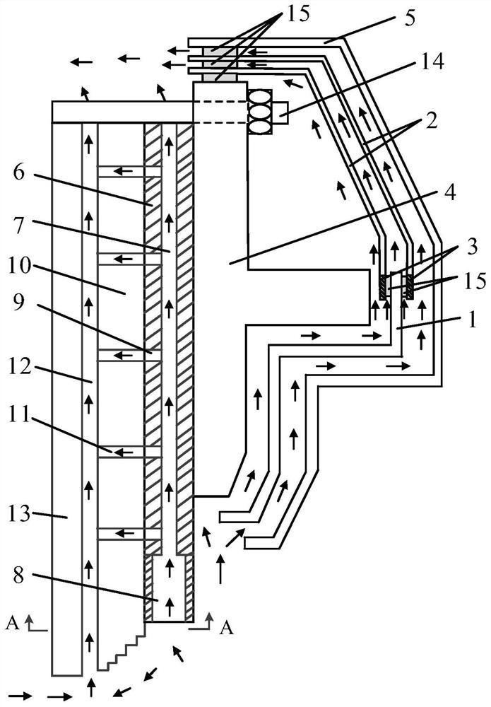
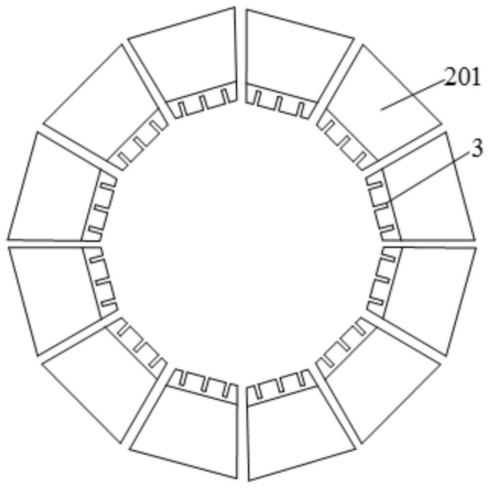
[0031] Such as Figure 1~4 as well as Figure 7 As shown, the present invention provides a large-capacity synchronous condenser end loss reduction ventilation device, which includes a pressure ring 4 and a shielding layer 1. The material of the shielding layer 1 is preferably copper. The iron core 13 at the end of the camera is fixedly connected, and the front of the pressure ring 4 is provided with a double-layer shielding layer 2 in a hollow structure, and the double-layer shielding layer 2 is fixedly connected with the pressure ring 4, such as figure 2 As shown, the double-layer shielding layer 2 is a dome structure with a through hole in the middle, and each layer of the double-layer shielding layer 2 includes 12 fan-shaped shielding layers 201, and a gap is provided between two adjacent fan-shaped shielding layers 201. The width of the double-layer shielding layer 2 is 4-6mm, the gaps on each layer of the double-layer shielding layer 2 do not overlap, the thickness of e...

Embodiment 2

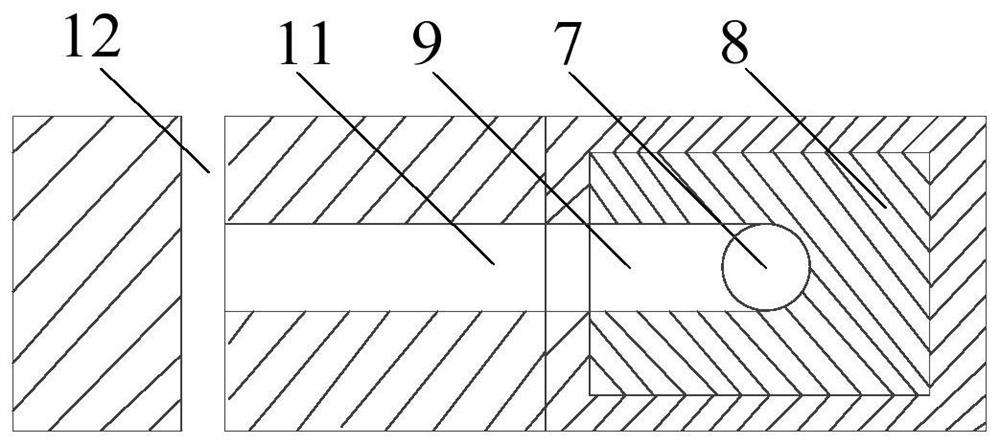
[0036] Such as figure 2 , image 3 , Figure 5 , Figure 7 with Figure 8 As shown, this embodiment is further limited on the basis of Implementation 1. The shape of the bottom ventilation cavity 8 is a circular platform structure, the small end of the bottom ventilation cavity 8 is connected to the middle ventilation cavity 7, and the depth of the bottom ventilation cavity 8 is 140 ~ 180mm, the centerline of the bottom ventilation cavity 8 coincides with the centerline of the middle ventilation cavity 7. The bottom ventilation cavity 8 inside the ventilation pressure finger 6 is in the shape of a truncated cone, which increases the contact area of ​​the bottom ventilation cavity 8, increases the flow rate of the cooling fluid from the bottom ventilation cavity 8 into the middle ventilation cavity 7, and reduces the fluid resistance, which is conducive to better heat dissipation.

Embodiment 3

[0038] Such as figure 2 , Image 6 , Figure 7 with Figure 9 As shown, this embodiment is further limited on the basis of implementation 1. The shape of the bottom ventilation cavity 8 is a rectangular groove structure, the depth of the bottom ventilation cavity 8 is 140-180mm, and the width of the bottom ventilation cavity 8 is 2-4mm; The bottom ventilation cavity 8 is set in a rectangular groove structure, which can better extend the flow path of the induced eddy current, thereby reducing the eddy current loss of the ventilation cavity 8 at the bottom of the ventilation pressure finger 6 and reducing the temperature rise.


PUM


Abstract

The invention discloses a large-capacity synchronous condenser end loss reduction ventilation device, which comprises a pressure ring, a shielding layer outside the pressure ring, a double-layer shielding layer connected with the shielding layer, an insulating windshield outside the shielding layer, a ventilation pressure finger, Magnetic shielding, positioning ribs. By setting double-layer shielding layer, an insulating pad is set between the double-layer shielding layer and the shielding layer, the pressure ring and the insulating windshield, the ventilation pressure finger is equipped with a ventilation cavity and multiple axial air ducts, and the magnetic shield is equipped with multiple ventilation The hole coincides with the central line of the axial ventilation duct of the ventilation pressure finger, which effectively improves the distribution of the electromagnetic field at the end of the large-capacity synchronous condenser, and reduces the pressure ring, the end positioning rib and the end ventilation pressure finger. The eddy current loss changes the wind direction flow at the end, reduces the maximum temperature in the end structural parts, enhances the cooling effect of the end structural parts of the synchronous condenser, ensures the safety performance of the synchronous condenser, and has a simple structure and is easy to implement.

Description

technical field [0001] The invention relates to the technical field of synchronous motors, in particular to a loss-reducing ventilation device at the end of a large-capacity synchronous condenser. Background technique [0002] Due to the characteristics of energy and power load distribution in my country, the UHV DC transmission system has been rapidly developed and widely used. Prominent problems such as weak DC sending end and insufficient short-circuit capacity have been threatening the safe and stable operation of the UHV DC transmission system. In order to deal with the reactive power adjustment problems brought about by UHVDC transmission and emerging energy access to the grid, large-capacity synchronous condensers have been used as an indispensable component in today's power grids due to their strong instantaneous reactive power support and short-term overload capabilities. Reactive power compensation equipment. Today, 300Mvar-class large-capacity synchronous conden...

Claims


Application Information

Patent Timeline
Patent Type & Authority Patents(China)
IPC IPC(8): H02K1/20H02K11/01H02J3/18
CPCH02J3/1885H02K1/20H02K2213/03H02K11/01Y02E40/30
Inventor 梁艳萍朱二夯
Owner HARBIN UNIV OF SCI & TECH
Why Eureka
Try Eureka