Air energy heat pump steam unit

An air-energy heat pump and steam unit technology, applied in heat pumps, energy-saving heating/cooling, refrigerators, etc., can solve the problem that air-energy heat pumps cannot meet specific needs, achieve convenient transfer and reuse, improve comprehensive utilization, increase The effect of a large contact area

Pending Publication Date: 2021-03-26
贵州九鼎新能源科技开发有限公司
View PDF0 Cites 2 Cited by
  • Summary
  • Abstract
  • Description
  • Claims
  • Application Information

AI Technical Summary

Problems solved by technology

[0004] Aiming at the deficiencies of the existing technology, the technical problem solved by the present invention is to provide an air source heat pump steam unit, solve the problem that the existing air source heat pump cannot meet the specific demand for higher temperature, and improve the heat conversion collection and reuse of the air source heat pump

Method used


Image

  • Air energy heat pump steam unit
  • Air energy heat pump steam unit
  • Air energy heat pump steam unit

Examples


Embodiment 1

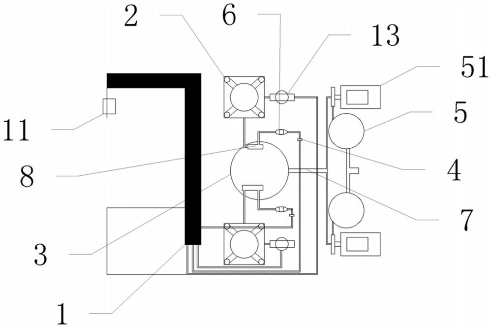
[0019] Embodiment 1 is basically as figure 1 Shown:

[0020] The air energy heat pump steam unit includes: evaporator 1, compressor 2, plate changer, throttling device 4, evaporator 1 is connected to compressor 2, plate changer 8 and throttling device 4 in sequence through pipelines, evaporator 1 and A gas-liquid separator 13 is provided between the compressors 2, an external fan 11 that can promote the exchange of cold air generated by the evaporator with external hot air is provided outside the evaporator 1, and a plate exchanger 8 for heat exchange is provided in the heat preservation water tank 3 Inside, a filter 6 is provided between the plate changer 8 and the throttling device 4, the throttling device 4 communicates with the evaporator 1 through a pipeline, and the thermal insulation water tank 3 uses the water supply pipe network 7 to connect with the steam generator through a high-pressure water supply booster pump 51 5. The water inlet 52 is connected.

[0021] Suc...

Embodiment 2

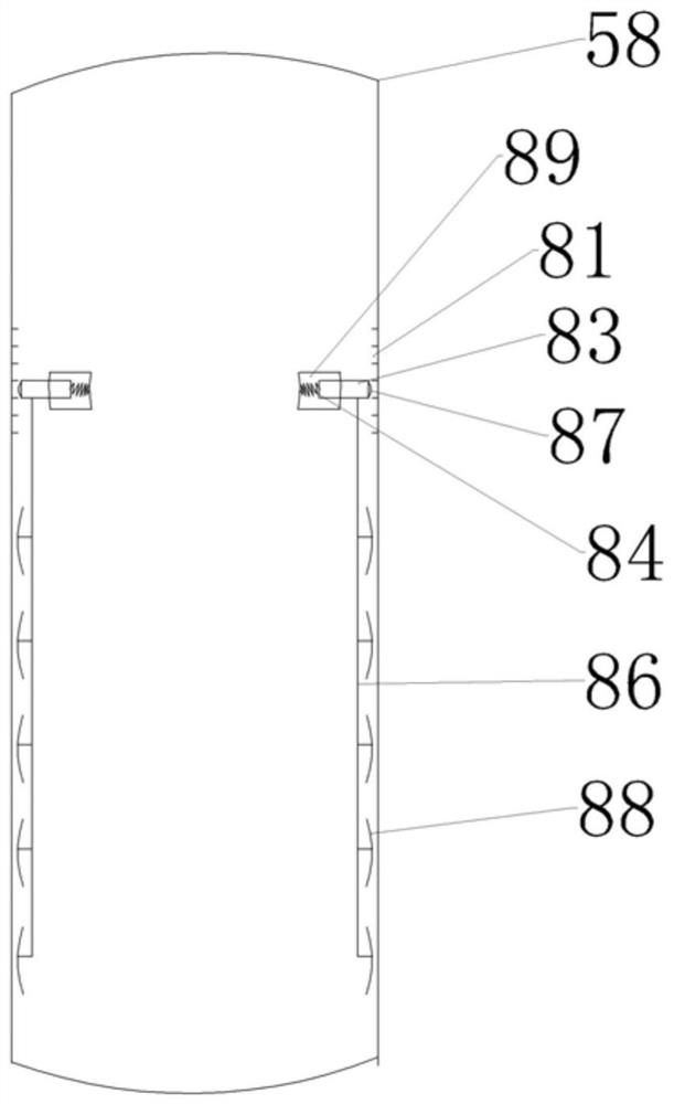
[0027] Embodiment 2 is as the further optimization to embodiment 1, as image 3 As shown: the steam generator 5 also includes a scale treatment device, and the scale treatment device includes: a threaded groove 81, a hollow floating ring 89, a slider 83, a spring 84, a connecting rod 86, a first scraper 87, a second scraper 88, Thread groove 81 is arranged on steam generator 5 tank inner walls, and hollow floating ring 89 is evenly provided with four openings, and slide block 83 is arranged in the opening, seals by sealing ring between slide block and opening, and one end of slide block 83 and spring 84 is fixedly connected, the other end of the spring 84 is fixedly connected to the inner side wall of the hollow floating ring 89, the bottom of the slider 83 is fixedly connected to one end of the connecting rod 86, and the connecting rod 86 is provided with a plurality of second scrapers 88.

[0028] When the steam generator 5 was working, the hollow floating ring 89 floated on...


PUM


Abstract

The invention relates to the technical field of air energy heat pump equipment, and particularly discloses an air energy heat pump steam unit. The air energy heat pump steam unit comprises an evaporator, a compressor, a plate exchanger and a throttling device, wherein the evaporator sequentially communicates with the compressor, the plate exchanger and the throttling device through pipelines; andthe plate exchanger for heat exchange is arranged in a heat preservation water tank, and the heat preservation water tank is connected with a steam generator for vaporizing liquid. The invention aimsto provide the air energy heat pump steam unit for solving the problems that an existing air energy heat pump cannot meet the specific requirement for higher temperature, and heat conversion, collection and reutilization of the air energy heat pump need to be improved.

Description

technical field [0001] The invention belongs to the technical field of air energy heat pump equipment, in particular to an air energy heat pump steam unit. Background technique [0002] When mentioning clean energy, most people first think of wind, light and water. In recent years, with the increasing energy consumption of building heating, cooling and hot water, "air energy" has become a new field that has received increasing attention in the process of China's clean energy development. The so-called "air energy" refers to the low-grade heat energy contained in the air, which belongs to clean energy like water energy, wind energy, solar energy and tidal energy. In 2009, the EU passed a decree to include air source heat pumps (air heat energy) into the category of renewable energy technologies, and defined air heat energy as the energy existing in the ambient air. With the development of technology, a variety of air source heat pump technology research and development Equi...

Claims


Application Information

Patent Timeline
IPC IPC(8): F22B37/48F24H4/04F24H9/18F24H9/20F25B30/02F25B30/06F25B43/00F25B49/02
CPCF22B37/48F24H4/04F24H9/1809F24H9/2007F25B30/02F25B30/06F25B43/00F25B49/02Y02B30/52
Inventor 陈丽陈洪
Owner 贵州九鼎新能源科技开发有限公司
Why Eureka
Try Eureka