
A drive shaft with a dust-proof oil seal structure

A technology for transmission shaft and dust-proof oil, applied in the field of auto parts, can solve the problems of reducing the sealing performance of the oil seal, failing to maintain the sealing performance of the oil seal, and degeneration and damage of the oil seal.

Active Publication Date: 2022-04-29
NINGBO JIECHENG AXLE TRADE
View PDF6 Cites 0 Cited by
  • Summary
  • Abstract
  • Description
  • Claims
  • Application Information

AI Technical Summary

Problems solved by technology

[0003] The oil seal generally needs an interference fit with the output shaft or / and the input shaft. When installing the oil seal, it is necessary to use tools such as a hammer to knock the oil seal to the installation position. Since it is impossible to ensure that the tool hits all parts of the oil seal evenly, it can ensure that the oil seal All parts of the oil seal can be located in the installation position, resulting in poor installation accuracy and unable to maintain the tightness of the oil seal. At the same time, parts of the oil seal are easily denatured and damaged due to excessive knocking force during installation.
[0004] For the oil seal installed on the transmission shaft, since the transmission shaft is a rotating body with high speed and few supports, it is easy to cause the oil seal with interference fit to wear, because there is no fixed position for installing the oil seal on the surface of the general transmission shaft , resulting in a gap between the oil seal and the transmission shaft after long-term use, which greatly reduces the sealing performance of the oil seal

Method used


Image

  • A drive shaft with a dust-proof oil seal structure
  • A drive shaft with a dust-proof oil seal structure
  • A drive shaft with a dust-proof oil seal structure

Examples


Embodiment 1

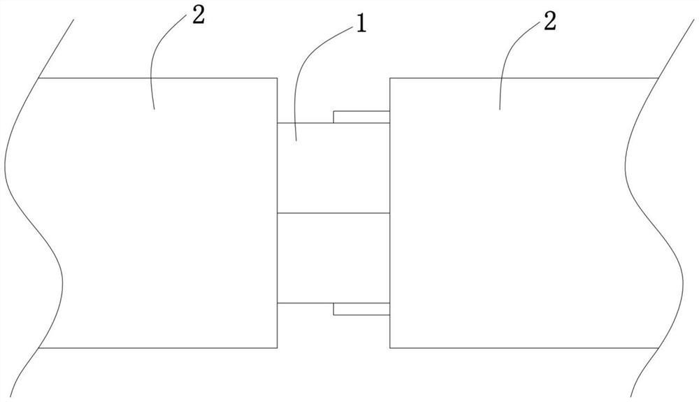
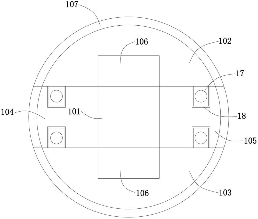
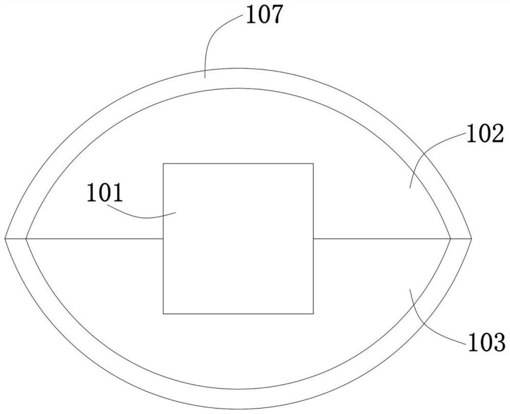
[0035] Such as Figure 1 to Figure 5As shown, a transmission shaft with a dust-proof oil seal 3 structure, which includes a central shaft 1, and a main shaft 2 with an outer diameter smaller than the central shaft 1, which is arranged on both sides of the central shaft 1, and the central shaft 1 includes a transmission mechanism for driving The driving mechanism of the transmission mechanism and the connecting part 101 integrally formed with the main shaft 2 on both sides are slidably installed between the main shafts 2 and symmetrically arranged on the first arc-shaped block 102 and the second arc-shaped block 103 at the upper and lower ends of the connecting part 101 , the first movable piece 104 and the second movable piece 105 that are located at the left and right ends of the connecting portion 101, the connecting portion 101 is provided with a driving chamber 101a, and the driving mechanism is installed in the driving chamber 101a and is connected to the first arc-shaped ...

Embodiment 2

[0046] Such as Figure 7 and Figure 9 As shown, in this embodiment, one of the optimized designs is made on the basis of the above-mentioned embodiment 1. A torsion spring 15 is fixed on the first movable block 104 on the side of the guide plate 14, and any force arm of the torsion spring 15 is fixed. There is a baffle plate 16, and the baffle plate 16 is fixed with the guide plate 14 at the same time. When the first movable block 104 and the second movable block 105 are separated from the slot 201, the torsion spring 15 restores the deformation to drive the baffle plate 16, and the baffle plate 16 drives the guide plate 14 to move toward the step, so that the step can abut against the guide plate 14 again, preventing the first movable block 104 and the second movable block 105 from shifting.

Embodiment 3

[0048] Such as figure 2 As shown, the present embodiment makes one of the optimized designs on the basis of the above-mentioned embodiment 1, the first arc-shaped block 102 and the second arc-shaped block 103 are formed with clamping plates 17, the first movable block 104 and the second The movable block 105 is provided with a draw-in groove 18 that can be engaged with the clamp plate 17, and the clamp plate 17 and the draw-in groove 18 are provided with corresponding screw holes. After the oil seal 3 is installed, the first arc-shaped block 102, The second arc-shaped block 103 , the first movable block 104 and the second movable block 105 are fixed to each other, thereby avoiding relative movement and affecting the oil sealing effect of the oil seal 3 .


PUM


Abstract

The invention relates to a transmission shaft with a dust-proof oil seal structure, which includes a central shaft and a main shaft with an outer diameter smaller than the central shaft, which are arranged on both sides of the central shaft. The central shaft includes a transmission mechanism, a driving mechanism, a connecting part, and a The first arc-shaped block and the second arc-shaped block arranged at the upper and lower ends of the connecting part, the first movable block and the second movable block arranged at the left and right ends of the connecting part, and the driving mechanism is connected with the first arc-shaped block and the second arc-shaped block , the transmission mechanism is connected with the first movable block and the second movable block, the first arc-shaped block, the second arc-shaped block, the first movable block and the second movable block are spliced ​​into a central axis when they are close to each other, and stored when they are close to each other The oil tanks can communicate with each other, and an oil seal is sheathed on the oil storage tanks. The transmission shaft of the technical solution has a specific installation position for the oil seal, so as to ensure good sealing performance of the oil seal even in the case of long-term operation, and can realize quick installation of the oil seal.

Description

technical field [0001] The invention relates to the technical field of auto parts, in particular to a transmission shaft with a dustproof oil seal structure. Background technique [0002] Oil seal is the customary title of general seals, simply put, it is the seal of lubricating oil. It is a mechanical element used to seal grease. It isolates the parts that need to be lubricated from the output parts in the transmission parts, so that the lubricating oil will not leak. The seals for static seals and dynamic seals are called oil seals. [0003] The oil seal generally needs an interference fit with the output shaft or / and the input shaft. When installing the oil seal, it is necessary to use tools such as a hammer to knock the oil seal to the installation position. Since it is impossible to ensure that the tool hits all parts of the oil seal evenly, it can ensure that the oil seal All parts of the oil seal can be located in the installation position, resulting in poor install...

Claims


Application Information

Patent Timeline
Patent Type & Authority Patents(China)
IPC IPC(8): F16C3/02F16J15/16F16N7/00
CPCF16C3/023F16J15/16F16N7/00
Inventor 周季旭
Owner NINGBO JIECHENG AXLE TRADE
Learn More