
Energy-saving pressure stabilizing water pump

An energy-saving and voltage-stabilizing technology, applied in the direction of water saving, pumps, pump components, etc., can solve the problems of high pressure at the water outlet, troublesome installation and operation, and inability to use alone, so as to stabilize the water outlet pressure and reduce space occupation and use. cost, the effect of avoiding equipment damage

Active Publication Date: 2021-03-26
SHENZHEN XING RISHENG INDAL
View PDF9 Cites 0 Cited by
  • Summary
  • Abstract
  • Description
  • Claims
  • Application Information

AI Technical Summary

Problems solved by technology

Ordinary water pumps generally cannot be used alone in the pipe network, but must be equipped with a pressure stabilizing device, because when the water pump is working, it will change with the pressure and flow of water, which will cause changes in the pressure and head of the water pump outlet. After installing the water pump, install a voltage stabilizing device on the periphery of the water pump to ensure the stability of the water output from the water pump. Consider how to configure the voltage stabilizing device, which will make the installation and operation troublesome and increase the cost
And if it is not equipped with voltage stabilizing equipment, the water pump will easily cause excessive pressure at the water outlet during use, and when people cannot find out in time, it will cause problems such as leakage of the water pump. In view of this, we propose an energy-saving stabilized pressure water pump

Method used


Image

  • Energy-saving pressure stabilizing water pump
  • Energy-saving pressure stabilizing water pump
  • Energy-saving pressure stabilizing water pump

Examples


Embodiment Construction

[0017] The following will clearly and completely describe the technical solutions in the embodiments of the present invention with reference to the accompanying drawings in the embodiments of the present invention. Obviously, the described embodiments are only some, not all, embodiments of the present invention. Based on the embodiments of the present invention, all other embodiments obtained by persons of ordinary skill in the art without making creative efforts belong to the protection scope of the present invention.

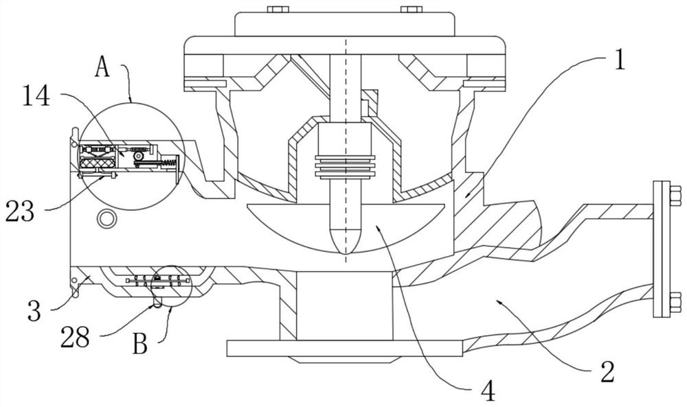
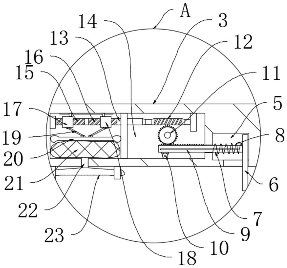
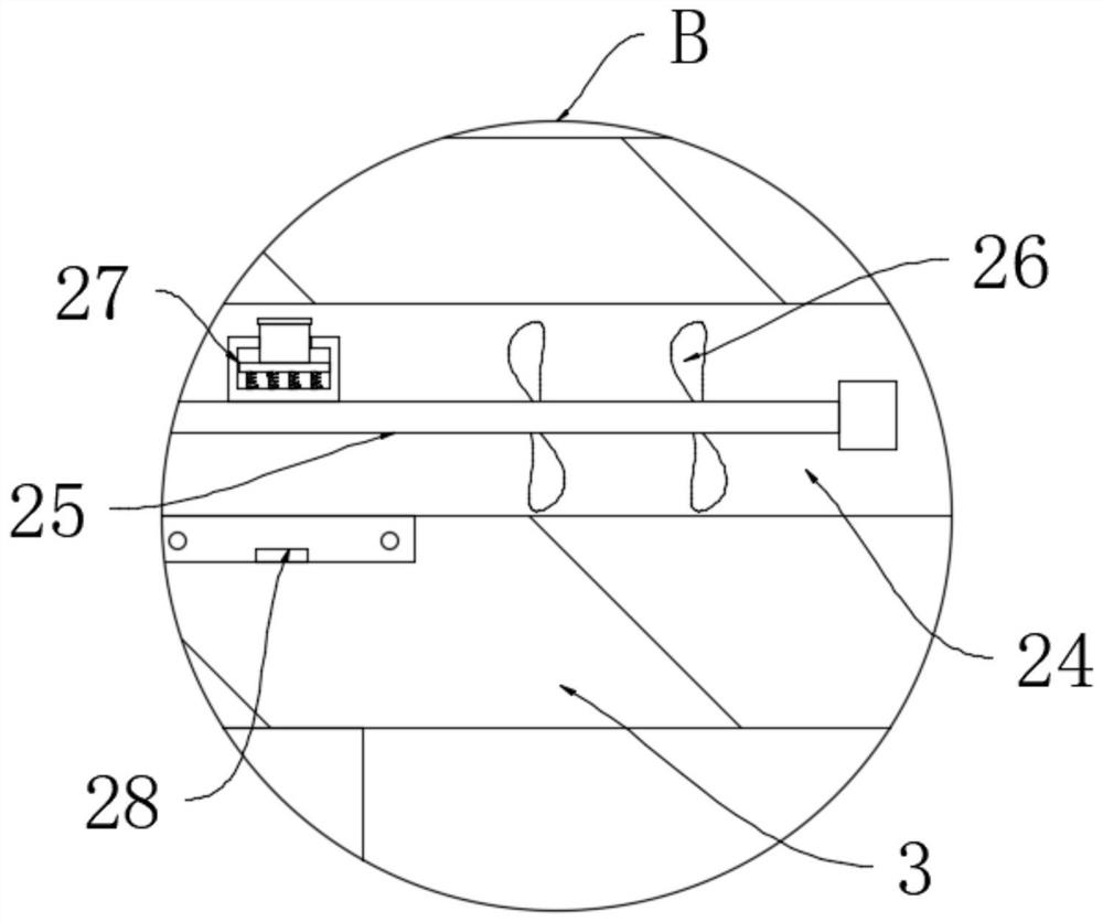
[0018] see Figure 1 to Figure 3 , the present invention provides a technical solution: an energy-saving stabilized pressure water pump, including a pump body 1, a water inlet 2 and a water outlet 3 are arranged on the pump body 1, and an impeller 4 is installed in the pump body 1, and an impeller 4 is installed on the water outlet 3 A chute 5 is provided, and a push plate 6 is slidably installed in the chute 5, a slide bar 7 is fixedly installed on the push p...


PUM


Abstract

The invention relates to the technical field of water pumps, in particular to an energy-saving pressure stabilizing water pump. The energy-saving pressure stabilizing water pump comprises a pump body,wherein a water inlet and a water outlet are formed in the pump body, and an impeller is arranged in the pump body; a sliding groove is formed in the water outlet, a push plate is arranged in the sliding groove in a sliding mode, a sliding rod is fixedly arranged on the push plate, and the sliding rod is sleeved with a spring; a rack is fixedly connected to the sliding rod, a guide wheel is arranged on the rack, a worm wheel is arranged on the rack in a meshed mode, a worm is arranged on the worm wheel in a meshed mode, a driving rod is coaxially connected to the worm, and the driving rod isarranged in a cavity in a rotating mode. An air bag type unpowered automatic pressure stabilizing mechanism is arranged in the water outlet of the pump body, water flow at the water outlet can be pressurized and depressurized within a certain range, the push plate is used for acting on a water pressure balance detection structure, and the form of an outer bag is changed, so that the water outlet area of the water outlet is automatically adjusted, and therefore the water outlet pressure of the water pump is stabilized.

Description

technical field [0001] The invention relates to the technical field of water pumps, in particular to an energy-saving stabilizing water pump. Background technique [0002] The water pump is the main water booster equipment, which plays many important hidden roles in people's daily life and provides convenience for people to use water. Ordinary water pumps generally cannot be used alone in the pipe network, but must be equipped with a pressure stabilizing device, because when the water pump is working, it will change with the pressure and flow of water, which will cause changes in the pressure and head of the water pump outlet. After installing the water pump, install a voltage stabilizing device on the periphery of the water pump to ensure the stability of the water output from the water pump. Consider how to configure the voltage stabilizing device, which will make the installation and operation troublesome and increase the cost. And if it is not equipped with voltage sta...

Claims


Application Information

Patent Timeline
IPC IPC(8): F04D1/00F04D29/66F04D15/00F04D29/42
CPCF04D1/00F04D29/669F04D15/0088F04D15/0027F04D29/4293Y02A20/00
Inventor 李家飞
Owner SHENZHEN XING RISHENG INDAL
Learn More