Manufacturing method of spatial cloth inflatable product, and spatial cloth inflatable product

A cloth inflatable, manufacturing method technology, applied in tents/canopies, building types, buildings, etc., can solve the problems that high-frequency welding technology cannot be applied

Active Publication Date: 2021-03-26
骆炳华
View PDF12 Cites 10 Cited by
  • Summary
  • Abstract
  • Description
  • Claims
  • Application Information

AI Technical Summary

Problems solved by technology

However, due to the wire drawing line between the two layers of the space cloth, the high-frequency welding process of the usual process conditions cannot be applied. At the same time, due to the high-frequency welding, it is usually necessary to place the mold to complete the welding. After welding, it is faced with the problem of how to remove the inner mold. A series of problems restrict people from considering the use of high frequency welding process to make this product

Method used


Image

  • Manufacturing method of spatial cloth inflatable product, and spatial cloth inflatable product
  • Manufacturing method of spatial cloth inflatable product, and spatial cloth inflatable product
  • Manufacturing method of spatial cloth inflatable product, and spatial cloth inflatable product

Examples


Embodiment 1

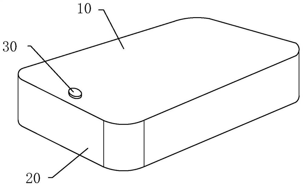
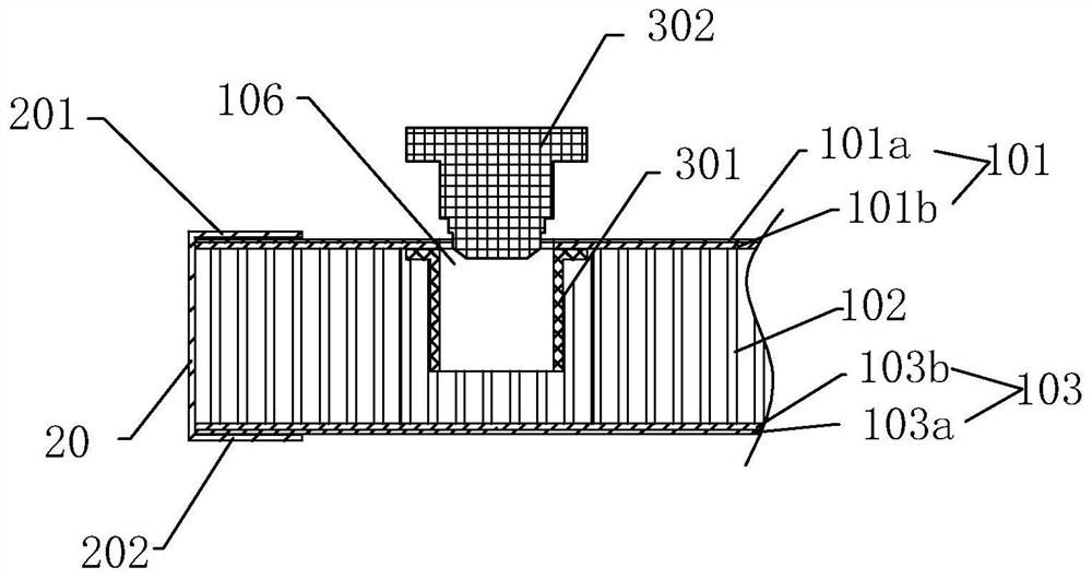
[0062] refer to Figure 1 to Figure 3 , the first embodiment provides a space cloth inflatable product, including a space cloth 10 and a bar 20, the space cloth 10 includes an upper base cloth 101 and a lower base cloth 103, and the upper base cloth 101 is arranged from top to bottom It includes an upper film layer 101a and an upper high-strength fabric layer 101b formed by composite processing, and the lower base fabric 103 includes a lower high-strength fabric layer 103b and a lower film layer 103a formed by composite processing from top to bottom, and the upper film layer 101a and the lower film layer 103a are both TPU film layers, the upper base cloth 101 and the lower base cloth 103 are fixedly connected by a plurality of drawing wires 102, and the surrounding bar 20 has a transverse direction along the length direction and a longitudinal direction along the width direction. Define the side edges of the surrounding bar 20 located on both sides of the longitudinal directio...

Embodiment 2

[0085] refer to Figure 3 to Figure 5 , the second embodiment provides a space cloth inflatable product, including a space cloth 10 and a bar 20, the space cloth 10 includes an upper base cloth 101 and a lower base cloth 103, and the space cloth 10 includes an upper base cloth 101 and the lower base cloth 103, the upper base cloth 101 includes an upper film layer 101a and an upper high-strength fabric layer 101b formed by composite processing from top to bottom, and the lower base cloth 103 includes a lower layer processed by composite processing from top to bottom. The high-strength fabric layer 103b and the lower film layer 103a, the upper film layer 101a and the lower film layer 103a are both PVC film layers, and the upper base cloth 101 and the lower base cloth 103 are fixedly connected by a plurality of drawing wires 102, so The surrounding bar 20 has a transverse direction along the length direction and a longitudinal direction along the width direction, and defines that...

Embodiment 3

[0104] refer to figure 2 , Figure 6 , Figure 7 , the third embodiment provides a space cloth inflatable product, including a space cloth 10 and a bar 20, the space cloth 10 includes an upper base cloth 101 and a lower base cloth 103, and the upper base cloth 101 is arranged from top to bottom It includes an upper film layer 101a and an upper high-strength fabric layer 101b formed by composite processing, and the lower base fabric 103 includes a lower high-strength fabric layer 103b and a lower film layer 103a formed by composite processing from top to bottom, and the upper film layer 101a and the lower film layer 103a are both TPU film layers, the upper base cloth 101 and the lower base cloth 103 are fixedly connected by a plurality of drawing wires 102, and the surrounding bar 20 has a transverse direction along the length direction and a longitudinal direction along the width direction. Define the side edges of the surrounding bar 20 located on both sides of the longitu...


PUM


Abstract

The invention relates to a manufacturing method of a spatial cloth inflatable product, and the spatial cloth inflatable product. The manufacturing method comprises the following steps of S1, preparingspatial cloth with an inflation hole; S2, preparing foxing strips; S3, comprising the following step (a1) of welding the foxing strips with lower-layer base cloth according to a conventional high-frequency welding process; the step (a2) of preparing a straight backing plate, a non-linear backing plate and a non-linear pressing plate matched with the non-linear backing plate, and taking the foxingstrip closest to the inflation hole and upper-layer base cloth as a final welding process; placing the straight backing plate or the non-linear backing plate on the inner surface of the upper-layer base cloth, and covering the upper side edge of the foxing strip on the outer surface of the upper-layer base cloth; welding the foxing strips with the upper-layer base cloth through a high-frequency machine; the step (a3) of arranging an inner shell of an inflation valve between the upper-layer base cloth and the lower-layer base cloth near the inflation hole; the step (a4) of welding the reservedfoxing strips with the upper-layer base cloth into a whole; the step (a5) of taking out the backing plate from the space cloth through the inflation hole; and the step (a6) of moving the inner shellto the inflation hole, and connecting an inflation valve body with the inner shell.

Description

technical field [0001] The invention relates to the technical field of space cloth inflatable products, in particular to a method for manufacturing a space cloth inflatable product and the space cloth inflatable product. Background technique [0002] Existing space cloth inflatable products include space cloth and apron. The surrounding strip is a long rectangular strip, and the two side edges of the surrounding strip are gradually welded to each other by hot air to form a whole. When the place to be welded is non-linear (that is, arc or corner), it is easy to produce more folds, that is, there are many gaps, and it cannot be welded by hot air. At this time, glue is used to connect. Such space cloth inflatable products are usually used for surfboards (such as the easy inflatable surfboard disclosed in patent application number CN201520428956.1) or tents (such as an inflatable tent disclosed in patent application number CN03102888.8) Wait. However, its shortcomings are also...

Claims


Application Information

Patent Timeline
IPC IPC(8): B29C65/04B29C65/78E04H15/20
CPCB29C65/04B29C65/7802E04H15/20E04H2015/205E04H2015/206
Inventor 骆炳华
Owner 骆炳华
Why Eureka
Try Eureka