Transmitting-receiving integrated high-speed signal light transmission device and signal light transmission method

A high-speed signal and optical transmission technology, applied in the field of communication systems, can solve the problems of poor environmental resistance, affecting the reliability of signal connection, and the principle circuit cannot be miniaturized.

Active Publication Date: 2021-03-23
安徽光纤光缆传输技术研究所
View PDF10 Cites 0 Cited by
  • Summary
  • Abstract
  • Description
  • Claims
  • Application Information

AI Technical Summary

Problems solved by technology

[0008] (1) In addition to the coupling circuit, laser modulation and driving circuit, and limiting amplifier circuit, the circuit also includes a microcontroller circuit. Therefore, the principle circuit cannot achieve the design purpose of miniaturization;
[0009] (2) The microcontroller circuit manages the laser modulation and driving circuit and the limiting amplifier circuit at the same time. Therefore, the transceiver channels cannot be electrically independent from each other, and the mutual crosstalk between the transceiver channels cannot be avoided;
[0010] (3) Both the optical and electrical interfaces are pluggable. The optical module is in an open state and cannot be used in shipboard and other application environments. poor environmental performance
[0011] In the existing technology, the scheme and structural design of the general-purpose optical module not only make the product bulky, but also have a complex structure, making it difficult to achieve the technical purpose of all-metal sealing for transceivers

Method used


Image

  • Transmitting-receiving integrated high-speed signal light transmission device and signal light transmission method
  • Transmitting-receiving integrated high-speed signal light transmission device and signal light transmission method
  • Transmitting-receiving integrated high-speed signal light transmission device and signal light transmission method

Examples


Embodiment Construction

[0119] The present invention is described in detail below with reference to accompanying drawing and embodiment:

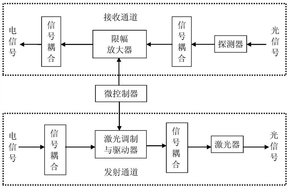
[0120] attached Figure 1-6 It can be seen that a high-speed signal optical transmission device integrating transceiver,

[0121] Including a housing, a signal receiving circuit 9 and a signal transmitting circuit 8 are arranged in the housing, and the signal receiving circuit includes: a detector, a signal coupling circuit, a limiting amplifier, and a signal coupling circuit; the detector receives an optical signal and converts the optical signal into an electrical signal The signal is transmitted to the signal coupling circuit, the limiting amplifier, and the signal coupling circuit in turn, and the electrical signal is output.

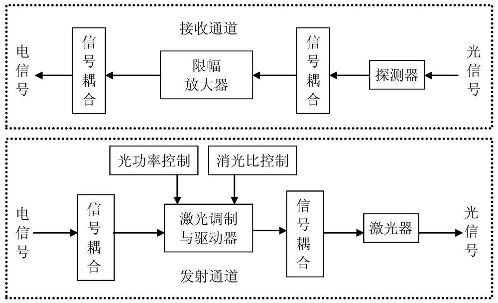
[0122] The signal transmitting circuit includes: signal coupling circuit, laser modulation and driving circuit, optical power control circuit, extinction ratio control circuit, signal coupling circuit and laser;

[0123] The input ele...


PUM


Abstract

The invention relates to a transmitting-receiving integrated high-speed signal optical transmission device which comprises a shell, a signal receiving circuit and a signal transmitting circuit are arranged in the shell, and the signal receiving circuit comprises a detector, a signal coupling circuit, a limiting amplifier and a signal coupling circuit; wherein the detector receives an optical signal, converts the optical signal into an electric signal and transmits the electric signal to the signal coupling circuit, the limiting amplifier, the signal coupling circuit and the output electric signal in sequence, and the signal transmitting circuit comprises a signal coupling circuit, a laser modulation and driving circuit, an optical power control circuit, an extinction ratio control circuit,a signal coupling circuit and a laser. According to the transmitting-receiving integrated high-speed signal optical transmission device, pure hardware setting is adopted, a microcontroller circuit isnot included in the circuit, stable control over optical power and extinction ratio and temperature compensation are achieved in a resistor matching mode, the anti-electromagnetic interference capacity is high, the structure is compact, the size is small, parallel use of multiple paths of signals is facilitated, and the environmental adaptability is high.

Description

technical field [0001] The invention relates to a communication system, in particular to a high-speed signal optical transmission device integrating transceiver and a signal optical transmission method. Background technique [0002] With the continuous development of 5G communication in my country, the amount of data to be processed and transmitted is also increasing, and the number of signal channels is also increasing. Although the pressure can be relieved to a certain extent by increasing the transmission rate of the signal, the transmission rate The improvement of optical transmission has brought problems such as crosstalk, and the increase in the number of signal channels has also increased the weight of the system, which is unacceptable for important communication systems. The advantages of optical transmission are fast speed, anti-interference, and light weight. Therefore, weapons The signal transmission mode of the system is also gradually converted from electricity to...

Claims


Application Information

Patent Timeline
Patent Type & Authority Applications(China)
IPC IPC(8): H04B10/40
CPCH04B10/40
Inventor 吴振刚天国周魏常
Owner 安徽光纤光缆传输技术研究所
Why Eureka
Try Eureka