
Execution system for driving automobile gearbox to shift gears

A technology for automotive gearboxes and executive systems, applied in the field of executive systems, can solve the problems of expensive software and hardware, complex and bloated structures, and complicated driving methods, and achieve the effects of low cost, compact layout, and simple structure

Pending Publication Date: 2021-03-23
智蔻科技(苏州)有限公司
View PDF0 Cites 0 Cited by
  • Summary
  • Abstract
  • Description
  • Claims
  • Application Information

AI Technical Summary

Problems solved by technology

Due to the small output torque of the brushed DC motor, a large transmission ratio is required to meet the torque requirements of the shift shaft of the drive gearbox. Therefore, the design of the transmission mechanism of 3 stages or above is usually used, resulting in a complex and bloated structure and low transmission efficiency. question
The output torque of the brushless DC motor is larger, and less transmission mechanisms can be used, but the cost of the brushless DC motor is more expensive, and the driving method is more complicated than that of the brushed DC motor, so the cost of software and hardware is expensive

Method used


Image

  • Execution system for driving automobile gearbox to shift gears
  • Execution system for driving automobile gearbox to shift gears
  • Execution system for driving automobile gearbox to shift gears

Examples


Embodiment

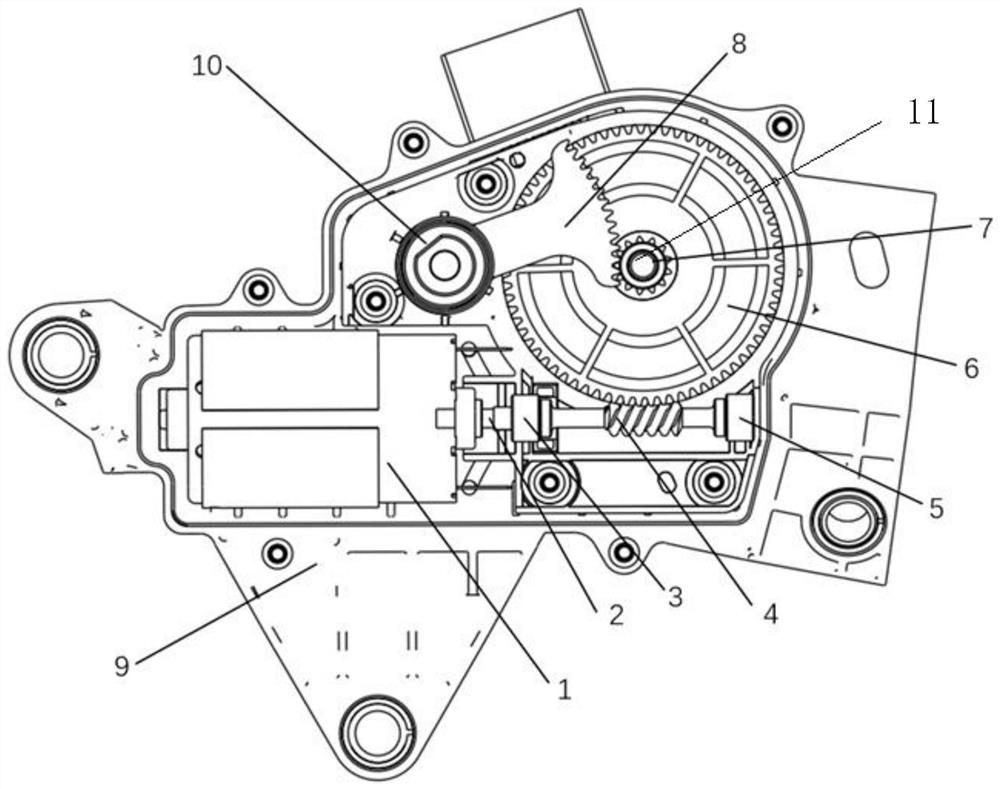
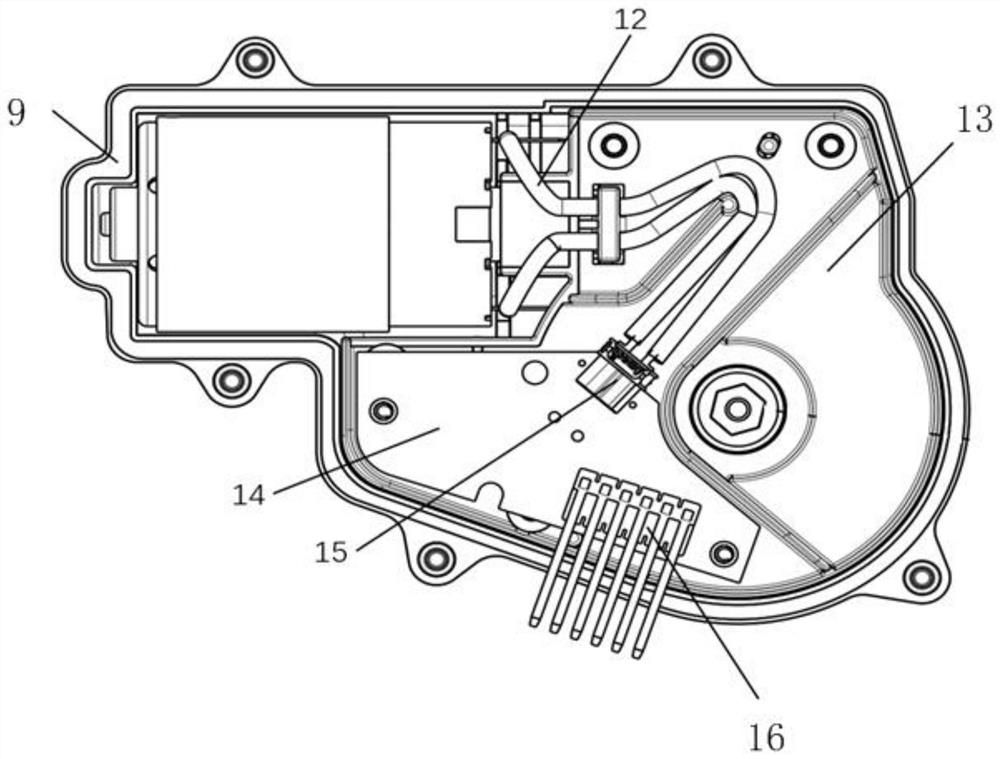
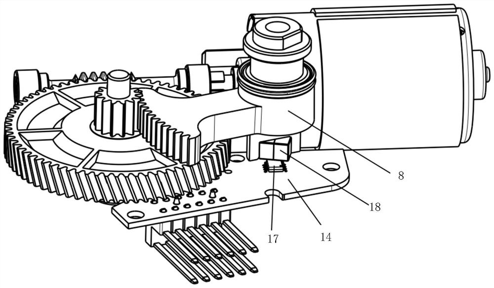
[0026] Such as Figure 1 to 3 As shown, an execution system for driving the automotive gearbox shift, includes a housing 9, a DC motor 1 is provided on one side of the casing 9, the DC motor 1 by output shaft 2 and a worm The 4 phase drive is connected, the worm 4 is located on the other side of the housing 9, and the housing 9 is provided with a turbine 6 by the rotating shaft 11, the turbine 6 is located above the worm 4, and the worm 4 is engaged with the turbine 6. A gear 7 is provided on the rotating shaft 11, and the gear 7 is also fitted at the center of the turbine 6, and the gear 7 is rotatably provided with the turbine 6, and the housing 9 is provided with a rotary output shaft 10, The sector gear 8 in which a synchronous rotation is provided on the rotation output shaft 10, and the sector gear 8 is provided with the gear 7, and the housing 9 is provided with a control circuit board 14, and the front side of the control circuit board 14 is set. With a sensor 17, a magnet ...


PUM


Abstract

The invention relates to an execution system for driving an automobile gearbox to shift gears. The execution system comprises a shell, a direct-current motor is arranged on one side of an inner cavityof the shell, the direct-current motor is in driving connection with a worm through an output shaft, the worm is positioned on the other side of the shell, a turbine is arranged in the shell througha rotating shaft, the turbine is positioned above the worm, and the worm meshes with the turbine; the rotating shaft is provided with a gear, the gear is further embedded in the center of the turbineand synchronously rotates along with the turbine, a rotating output shaft is arranged in the shell, the rotating output shaft is provided with a fan-shaped gear which synchronously rotates, the fan-shaped gear meshes with the gear, a control circuit board is arranged in the shell, and a sensor is arranged on the front face of the control circuit board; and the fan-shaped gear is provided with a magnet, the magnet is located above the sensor, when the fan-shaped gear rotates, the magnet is driven to rotate synchronously, and the magnet and the sensor are arranged in a matched mode. The performance of low cost, miniaturization, low noise and the like of the execution system is realized.

Description

Technical field [0001] The present invention relates to an execution system, and more particularly to an execution system for driving a shift shift shift. Background technique [0002] Currently, more and more vehicles use automatic gearboxes. The shift signal emitted by the driver needs to be converted into the rotation of the gearbox shift rotary shaft, thereby driving the gearbox to reach the specified gear. Then the execution system becomes a medium that shift signals and gearbox shifts. It can receive shift signals, converted to the small torque of the motor in the execution system to drive the shift shaft rotation of the transmission shaft by the internal transmission assembly. And rotate the appropriate angle, drive the gearbox to the appropriate position. The implementation system on the current market is classified according to the motor, which can be divided into two categories of brush DC motor and brushless DC motor. Due to the smaller output torque, a large transmiss...

Claims


Application Information

Patent Timeline
Patent Type & Authority Applications(China)
IPC IPC(8): F16H1/22F16H57/023F16H57/028F16H57/039F16H55/22F16H55/17F16H55/06F16H57/12F16H61/32F16H63/30
CPCF16H1/222F16H55/06F16H55/17F16H55/22F16H57/023F16H57/028F16H57/039F16H57/12F16H61/32F16H63/304
Inventor 陈荣戴稍进周波
Owner 智蔻科技(苏州)有限公司
Learn More