
Device and method for monitoring temperature change in frozen soil layer drilling process

A temperature change and monitoring device technology, which is applied in drilling equipment and methods, earthwork drilling, drilling equipment, etc., can solve the problems of inability to monitor the dynamic changes of the temperature of the frozen soil layer and affecting the experimental accuracy.

Pending Publication Date: 2021-03-23
CHINA PETROLEUM & CHEM CORP +2
View PDF3 Cites 4 Cited by
  • Summary
  • Abstract
  • Description
  • Claims
  • Application Information

AI Technical Summary

Problems solved by technology

[0003] Domestic research on permafrost drilling is basically in a blank state. A device for simulating drilling in permafrost is disclosed in CN108104716A, which is mainly used to simulate the drilling process in permafrost, including drill bits, drill strings and circulation devices. Including the drilling fluid circulation device, but there are still problems that the accuracy of the experiment is affected by the external temperature environment, and it is impossible to monitor the dynamic change of the temperature of the permafrost

Method used


Image

  • Device and method for monitoring temperature change in frozen soil layer drilling process
  • Device and method for monitoring temperature change in frozen soil layer drilling process
  • Device and method for monitoring temperature change in frozen soil layer drilling process

Examples


Embodiment Construction

[0032] Below in conjunction with accompanying drawing, the present invention is described in further detail:

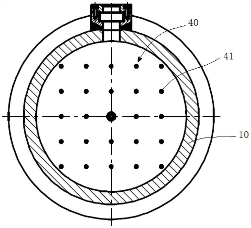
[0033] Such as Figure 1 to Figure 3 As shown, the present invention provides a monitoring device for temperature changes during drilling in permafrost, including: a low-temperature constant temperature test chamber 10, a double-layer circulation pipe 20, a drilling fluid circulation system 30, a temperature measurement system 40, and a data acquisition system 50.

[0034] The temperature in the low temperature constant temperature test chamber 10 can be controlled by a low temperature constant temperature water bath, the temperature control range is -15~90°C, and the control precision is 0.5°C. More specifically, the low temperature and constant temperature test chamber 10 is surrounded by a water jacket 11, and the cold water cycle can be carried out in the water jacket 11, and the temperature control of the low temperature and constant temperature test chamber 10 i...


PUM


Abstract

The invention provides a device and method for monitoring the temperature change in a frozen soil layer drilling process. The device comprises a low-temperature constant-temperature test box, a double-layer circulation pipe, a drilling fluid circulation system and a temperature measuring system, wherein sandy soil / clay with a preset moisture content is laid inside the low-temperature constant-temperature test box, and is used for forming a frozen soil simulation layer; at least a part of the double-layer circulation pipe is positioned in the low-temperature constant-temperature test box; the drilling fluid circulation system is connected with the double-layer circulation pipe and is used for enabling drilling fluid with the preset temperature to circulate in the double-layer circulation pipe; and the temperature measuring system is arranged in the low-temperature constant-temperature test box and is used for monitoring the temperature change condition of the frozen soil layer in the low-temperature test box in the whole drilling circulation process. The method comprises the following steps of preparing the frozen soil simulation layer in the low-temperature constant-temperature test box; performing drilling fluid circulation in the frozen soil simulation layer through the double-layer circulation pipe; and dynamically monitoring the temperature of the frozen soil simulation layer. The device and method provided by the invention have the advantages that the frozen soil simulation layer is prepared in the low-temperature constant-temperature test box, and the temperature change condition of the frozen soil layer in the low-temperature test box in the whole drilling circulation process can be completely monitored.

Description

technical field [0001] The invention belongs to the petroleum drilling industry, and in particular relates to a monitoring device for temperature change during drilling in permafrost layers. Background technique [0002] Large areas of permafrost are widely distributed in the shallow strata of the arctic and sub-arctic low-temperature regions. The permafrost covers land and sea, with a thickness ranging from tens of meters to hundreds of meters. However, drilling in permafrost is very difficult. One of the important problems is that during the drilling process, due to the heat exchange between the drilling fluid and other circulating media and the formation and the cutting friction between the drill bit and the formation, the pore ice in the permafrost melts and freezes. The bearing capacity of the soil is greatly reduced. Some wells in West Siberia gas fields in Russia have subsided due to the melting of permafrost, and the maximum subsidence depth exceeds 3m. Therefore, m...

Claims


Application Information

Patent Timeline
IPC IPC(8): E21B7/00E21B47/07E21B21/00E21B49/00
CPCE21B7/008E21B21/00E21B49/00
Inventor 王磊柯珂李莅临杨进张辉张东清徐东升
Owner CHINA PETROLEUM & CHEM CORP
Learn More