
Efficient precipitated particle grinding device for textile fabric dyeing

A technology of textile fabrics and grinding devices, which is applied to mixers with rotating stirring devices, transportation and packaging, mixers, etc., can solve problems such as waste, easy sedimentation, and low efficiency, and reduce manufacturing costs and failure rates. Grinding Better effect, simple and convenient operation

Inactive Publication Date: 2021-03-23
SUZHOUBIDAER INNOVATION MATERIALS TECH CO LTD
View PDF10 Cites 0 Cited by
  • Summary
  • Abstract
  • Description
  • Claims
  • Application Information

AI Technical Summary

Problems solved by technology

[0003] At present, during the dip-dyeing process of the existing textile fabrics, because the paint color particles are easy to precipitate, resulting in uneven dyeing of the textile fabrics, the existing process is to screen and discharge the paint particles, which is inefficient and wasteful. At the same time, the screening is not thorough enough. Grinding the screened paint particles once, the grinding effect is not good, the equipment structure is complicated, which affects the uniformity of material dyeing, and the failure rate for different sizes of paint particles is high

Method used


Image

  • Efficient precipitated particle grinding device for textile fabric dyeing
  • Efficient precipitated particle grinding device for textile fabric dyeing
  • Efficient precipitated particle grinding device for textile fabric dyeing

Examples


Embodiment Construction

[0026] In order to make the object, technical solution and advantages of the present invention clearer, the present invention will be further described in detail below in combination with specific embodiments and with reference to the accompanying drawings. It should be understood that these descriptions are exemplary only, and are not intended to limit the scope of the present invention. Also, in the following description, descriptions of well-known structures and techniques are omitted to avoid unnecessarily obscuring the concept of the present invention.

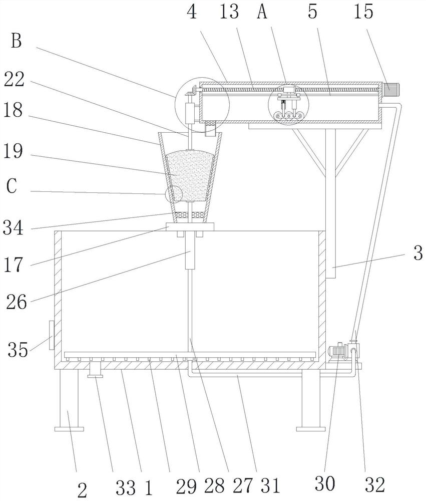
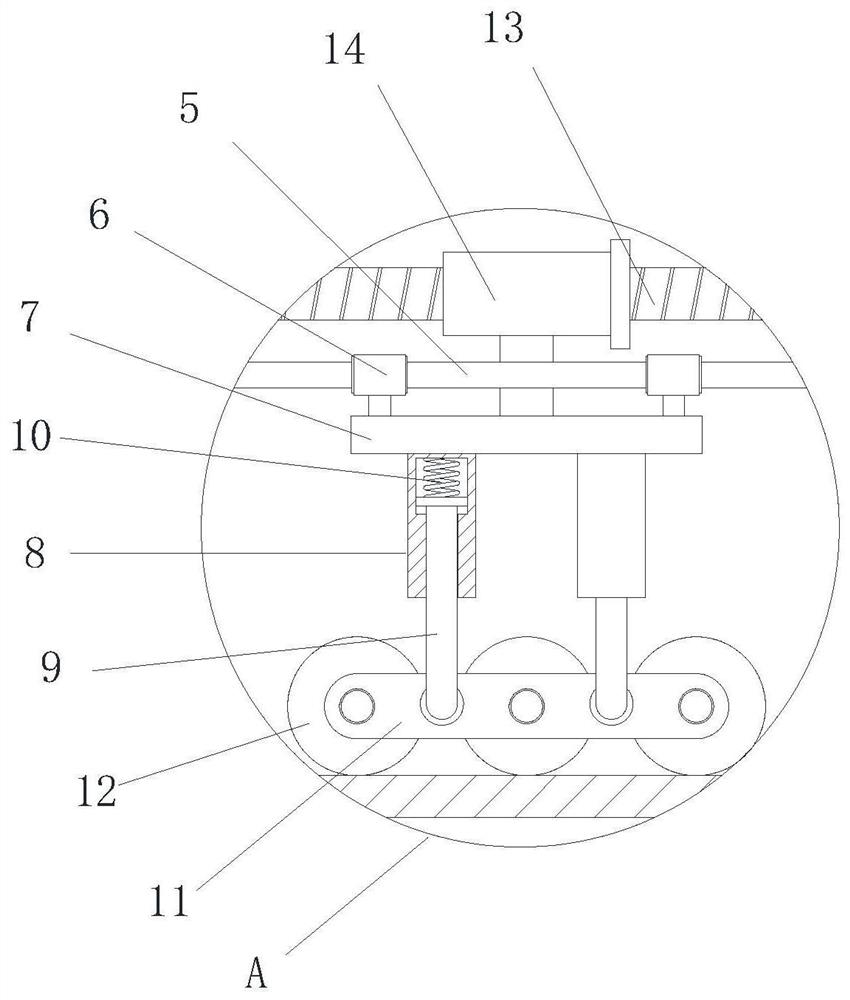
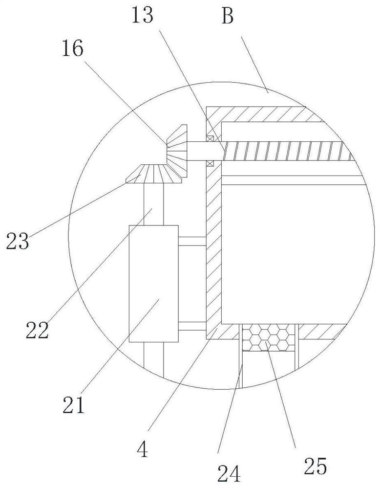
[0027] Such as Figure 1-4 As shown, a high-efficiency grinding device for sedimentation particles for dyeing textile fabrics proposed by the present invention includes a dyeing box 1, a rectangular box 4 and a grinding cylinder 18. A number of support legs 2 are arranged on the left and right edges of the lower end of the dyeing box 1, The left side of the lower end of the dyeing box 1 is provided with a drain pipe 33, ...


PUM


Abstract

An efficient precipitated particle grinding device for textile fabric dyeing comprises a dyeing box, a rectangular box and a grinding cylinder, a support is arranged in the upper side of the right endof the dyeing box, a supporting plate is arranged at the upper end of the support, the rectangular box is arranged at the upper end of the supporting plate, a plurality of guide rods are arranged inthe upper side of the interior of the rectangular box, guide sleeves are in sliding connection to the middle of the guide rods respectively, the lower sides of the peripheral faces of the guide sleeves are jointly connected with a movable plate, multiple elastic buffer modules are arranged on the front side and the rear side of the lower end of the movable plate, and the lower end of the movable plate is connected with a fixed plate through the multiple elastic buffer modules. According to the invention, a servo motor serves as the only power, the equipment manufacturing cost and failure rateare reduced, dyeing particles at the bottom of the dyeing box can be comprehensively and thoroughly sucked away, cleaning is more thorough, fine dyeing particles subjected to double grinding and filtering can be evenly dispersed in the dyeing box, the precipitated particle grinding efficiency is higher, the grinding effect is better, and material dyeing is more uniform.

Description

technical field [0001] The invention relates to the technical field of textile printing and dyeing equipment, in particular to a high-efficiency grinding device for sedimentation particles used for textile fabric dyeing. Background technique [0002] The dyeing methods of textile fabrics can be divided into two types: exhaust dyeing and pad dyeing, and other textile dyeings are no less than these two. Dyeing is roughly divided into five stages, namely bulk fiber dyeing, top dyeing, yarn dyeing, piece dyeing and garment dyeing. Regardless of woven fabrics or knitted fabrics, piece dyeing accounts for the highest proportion, followed by yarn dyeing, which complements other dyeing methods to create a colorful fashion; A dyeing method in which fibers are dyed and fixed in the fibers. Pad dyeing is to soak the textile fabric in the dye solution for a short time, and then press it with a roll to squeeze the dye solution into the interstitial space of the fabric, and remove the e...

Claims


Application Information

Patent Timeline
Patent Type & Authority Applications(China)
IPC IPC(8): B01F13/10B01F3/22B01F7/18B02C2/10B02C4/12B02C21/00B02C23/16B01F23/80
CPCB02C21/00B02C2/10B02C23/16B02C4/12B02C2023/165B01F23/81B01F27/90B01F33/83B01F33/83613
Inventor 王明辉
Owner SUZHOUBIDAER INNOVATION MATERIALS TECH CO LTD
Learn More