
Snow shovel

A snow shovel and shovel block technology, applied in the field of snow shovels, can solve problems such as large limitations, poor snow removal effect, and impact on traffic safety, and achieve the effects of reducing use limitations, improving snow shoveling effects, and improving stability

Active Publication Date: 2021-03-19
国网新疆电力有限公司博尔塔拉供电公司
View PDF11 Cites 0 Cited by
  • Summary
  • Abstract
  • Description
  • Claims
  • Application Information

AI Technical Summary

Problems solved by technology

Each snow removal method has certain advantages and limitations. The snow removal method of snow melting and snow removal is suitable for situations with a small amount of snow, but when faced with large areas of snow accumulation such as airport runways and roads, its snow removal effect is poor. Manual snow removal is used to remove snow, but the cost of manual removal is high and the efficiency is low, which affects traffic order and driving safety
[0003] Therefore, mechanical snow removal can achieve the effect of high-speed snow removal, and the impact on traffic order is relatively low. It is only suitable for flat asphalt roads or cement roads, etc., and has relatively large limitations. When encountering stone slabs or bricks, etc., the existing snow shovel cannot be completely cleaned due to the cracks between the bricks. , in the process of snow shoveling, the snow will be compacted in the cracks to form ice cubes, which will affect the traffic safety, so corresponding improvements are made to solve this problem

Method used


Image

  • Snow shovel
  • Snow shovel
  • Snow shovel

Examples


Embodiment 1

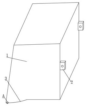
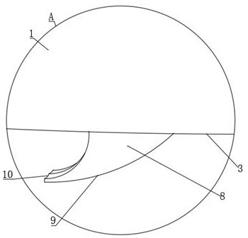
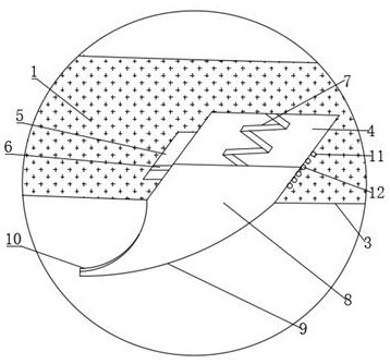
[0027] refer to Figure 1-3 , a snow shovel, comprising a snow shovel body 1, a plurality of mounting blocks 2 fixed to one side of the snow shovel body 1 by bolts, mounting holes are provided on the mounting blocks 2, the front section of the snow shovel body 1 is set as a trapezoid, and the snow shovel body The bottom of the shovel body 1 is provided with a first arc-shaped portion 3, and the bottom of the first arc-shaped portion 3 is provided with a plurality of installation grooves 4 evenly distributed in the longitudinal direction. The first spring 7 is fixed in the installation groove 4 by bolts, and the bottom of the first spring 7 is The shovel block 8 is fixed by bolts, the inner wall of the installation groove 4 is provided with a limit groove 5, and the limit block 6 is slidably connected in the limit groove 5, and the limit block 6 and the shovel block 8 are fixedly connected by bolts, and the shovel block 8 The bottom is provided with a second arc-shaped part 9, ...

Embodiment 2

[0031] refer to Figure 1-5 , a snow shovel, the bottom of the second arc portion 9 is provided with a plurality of embedding grooves 13 distributed in an annular array, the embedding grooves 13 are rotatably connected with a roller 14, and the outer wall of the roller 14 is welded with a plurality of rows distributed in an annular array Snowboard 15, snow expelling plate 15 sections are set to crescent shape.

[0032] In the present invention, the inner arc surface of the snow ejector 15 is provided with a booster portion 16, and the cross section of the booster portion 16 is arranged in a wave shape, which can increase the roughness of the surface of the snow ejector 15, thereby turning the snow farther.

[0033] In the present invention, the cut-off plate 17 is welded to the bottom of the snow discharge plate 15, and the bottom of the cut-off plate 17 is set in a pointed shape, which can cut off the hard snow blocks, so that the snow discharge plate 15 can turn the snow blo...

Embodiment 3

[0036] refer to Figure 1-6 , a kind of snow shovel, one end of the snow shovel body 1 is fixed with a box by bolts, a plurality of guide grooves are provided inside the snow shovel body 1, and the guide grooves are respectively connected with the box body and the installation groove 4, and the top of the shovel block 8 is provided with In the collecting chamber, a material guide pipe 18 is arranged inside the shovel block 8, and a discharge mechanism is arranged at the bottom of the material guide pipe 18.

[0037] In the present invention, a groove 19 is provided on the inner wall of one side of the embedding groove 13 of the discharge mechanism, and a second spring 20 is fixed in the groove 19 by bolts, and a clamping rod 21 is fixed on the other side of the second spring 20 by bolts. It is slidably connected with the groove 19, and a material leakage port 22 is opened through the clamping rod 21. The clamping rod 21 is in natural contact with the snow discharge plate 15, s...


PUM


Abstract

The invention belongs to the technical field of snow shoveling supplies, particularly relates to a snow shovel, and provides the following scheme for solving the problem that an existing snow shovel is large in use limitation: the snow shovel comprises a snow shovel body, the main view section of the snow shovel body is trapezoidal, a first arc-shaped part is arranged at the bottom of the snow shovel body, and a plurality of mounting grooves are formed in the bottom of the first arc-shaped part; a first spring is fixed in each mounting groove, a shovel block is fixed to the bottom of the firstspring, a limiting groove is formed in the inner wall of one side of each mounting groove, a limiting block is slidably connected into each limiting groove and fixedly connected with one shovel block, a second arc-shaped part is arranged at the bottom of each shovel block, a discharging part is arranged at the top of each shovel block, and the side view section of the discharging part is herringbone. According to the snow shovel, when the snow shovel body shovels snow, the shovel block located in the crack can extend into the crack under the action of the first spring, the snow in the crack is shoveled out along with pushing of the snow shovel body, so that the snow shovel can be suitable for various road shapes, and the use limitation is reduced.

Description

technical field [0001] The invention relates to the technical field of snow shoveling supplies, in particular to a snow shovel. Background technique [0002] Snow accumulation on roads brings a lot of inconvenience and troubles to traffic and people's travel, work, and life. In severe cases, it will also cause safety hazards. At present, the main snow removal methods in my country include snow melting, manual snow removal, and mechanical snow removal. Each snow removal method has certain advantages and limitations. The snow removal method of snow melting and snow removal is suitable for situations with a small amount of snow, but when faced with large areas of snow accumulation such as airport runways and roads, its snow removal effect is poor. The snow is removed by manual snow removal, but the cost of manual removal is high and the efficiency is low, which affects the traffic order and driving safety. [0003] Therefore, mechanical snow removal can achieve the effect of h...

Claims


Application Information

Patent Timeline
IPC IPC(8): E01H5/06E01H10/00
CPCE01H5/06E01H5/061E01H10/007
Inventor 胡孟凡
Owner 国网新疆电力有限公司博尔塔拉供电公司
Learn More