Mounting structure of condensing equipment

A technology for installing structures and condensing equipment, applied in lighting and heating equipment, steam/steam condensers, chemical/physical/physical-chemical processes, etc. and other problems, to achieve the effect of good connection effect, long service life and easy alignment

Inactive Publication Date: 2021-03-16
YIWU INDAL & COMMERICAL COLLEGE
View PDF1 Cites 0 Cited by
  • Summary
  • Abstract
  • Description
  • Claims
  • Application Information

AI Technical Summary

Problems solved by technology

[0004] The purpose of the present invention is to provide an installation structure for condensing equipment, which solves the problem that the usual installation method in the prior art is vertical installation. When connecting at the interface connection, the airtightness of the interface connection effect is affected because the pipelines are not easy to align. Problems that cause the equipment not to work normally and affect the service life

Method used


Image

  • Mounting structure of condensing equipment
  • Mounting structure of condensing equipment
  • Mounting structure of condensing equipment

Examples


Embodiment Construction

[0020] In order to make the object, technical solution and advantages of the present invention clearer, the present invention will be further described in detail below in conjunction with the accompanying drawings and embodiments. It should be understood that the specific embodiments described here are only used to explain the present invention, not to limit the present invention.

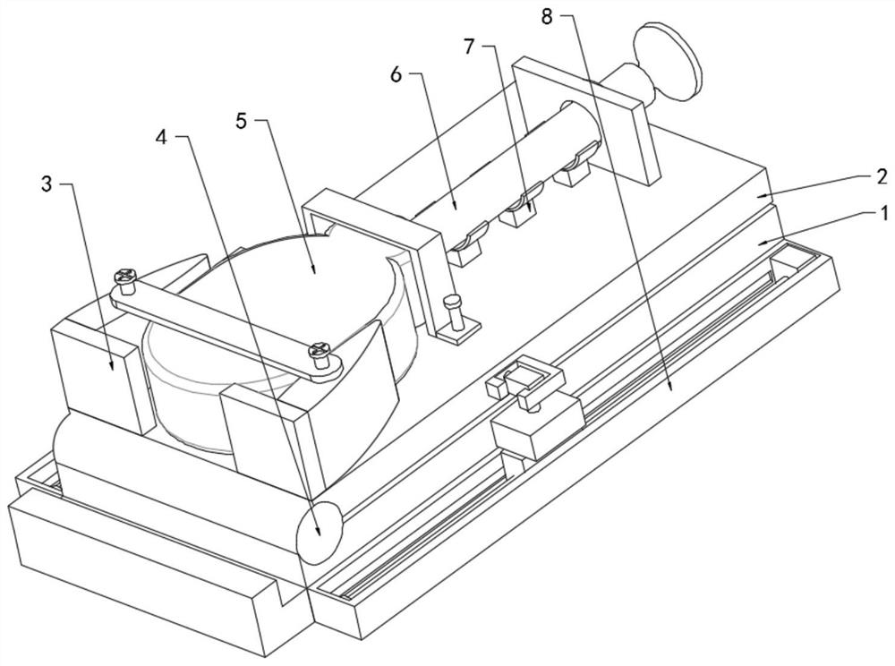
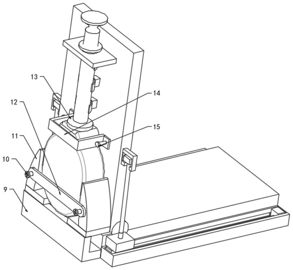
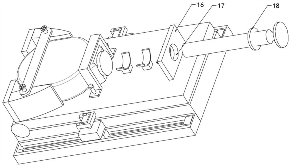
[0021] refer to Figure 1-4 , this embodiment discloses an installation structure of a condensing device, including a base plate 1, the base plate 1 is connected with a bearing plate 2 through a rotating shaft 4, and two opposite baffle plates 3 are arranged on the top side of the bearing plate 2, and the base plate 1 The two side walls of each baffle plate are fixedly provided with a driving device 8, and the top of each baffle plate 3 is fixedly connected with a support side plate 11, and a reaction kettle 5 is arranged between the two support side panels 11, and the top of the reaction kettle 5 ...


PUM


Abstract

The invention relates to the technical field of condensers, in particular to a mounting structure of condensing equipment, and solves the problems that equipment cannot be normally used and the service life is influenced due to the fact that pipelines are not easy to align and the airtightness of the connector connecting effect is influenced when connection is carried out in the connector connecting position due to the fact that a common mounting mode in the prior art is vertical mounting. The mounting structure of the condensing equipment comprises a bottom plate, the bottom plate is rotationally connected with a bearing plate through a rotating shaft, two oppositely-arranged baffles are arranged on one side of the top of the bearing plate, the top of each baffle is fixedly connected witha supporting side plate, a reaction kettle is arranged between the two supporting side plates, a fixing plate is clamped to the top of the reaction kettle, the side view surface of the fixing plate is in an inverted-U shape, and the two ends of the fixing plate are fixedly connected with bearing plate bolts through second screws. By means of the horizontal mounting mode, alignment of pipeline connectors is facilitated, the connecting effect is good, the airtightness is good, equipment can be normally used after butt joint, and the service life is long.

Description

technical field [0001] The invention relates to the technical field of condensers, in particular to the installation structure of condensing equipment. Background technique [0002] In the production process of hydrides, it is generally necessary to react in the reactor and under specific process conditions. During the reaction, some materials will evaporate and be recovered through the condenser, and the gaseous material inlet at the bottom of the condenser and the gaseous material in the reactor Outlet connection, the outlet on the top of the condenser is connected to the discharge pipe, the condensed water inlet and condensed water outlet on the side of the condenser are also connected and fixed with the corresponding water circulation pipeline, so that the condenser is connected and fixed through its four interfaces, due to the weight of the condenser Heavy, the usual installation methods are all vertical installations, for example, Chinese utility model patent CN2094482...

Claims


Application Information

Patent Timeline
IPC IPC(8): F28B9/00B01J19/00
CPCB01J19/00F28B9/00
Inventor 朱堂葵陈剑飞宋连墨
Owner YIWU INDAL & COMMERICAL COLLEGE
Why Eureka
Try Eureka