
A double-layer double-door electric flap valve

A flap valve, electric technology, applied in the direction of lifting valve, valve details, valve device, etc., can solve the problems of inconvenient cleaning, easy accumulation of materials to block channels, and blocking of suction materials

Active Publication Date: 2022-06-21
ZHEJIANG HONGFENG MASCH EQUIP CO LTD
View PDF13 Cites 0 Cited by
  • Summary
  • Abstract
  • Description
  • Claims
  • Application Information

AI Technical Summary

Problems solved by technology

[0007] The purpose of the present invention is to provide a double-layer double-door electric flap valve to solve the above-mentioned background technology. The middle position of the internal passage is mostly provided with two cross-bracing beams for abutting against the seal. The beam will block the suction material inside the channel, causing the material to easily accumulate and block the channel, causing subsequent cleaning inconvenience. In addition, most double-door flap valves only have one opening and closing mode, synchronous opening and closing in the same direction or reverse Alternate opening and closing, the application is relatively simple

Method used


Image

  • A double-layer double-door electric flap valve
  • A double-layer double-door electric flap valve
  • A double-layer double-door electric flap valve

Examples


Embodiment 1

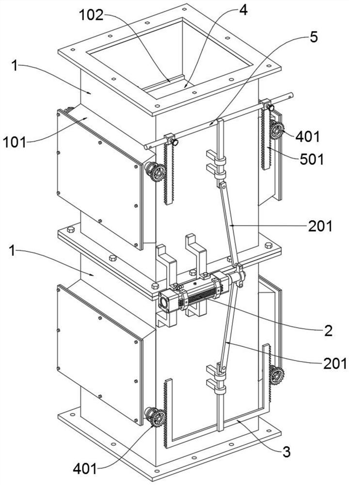
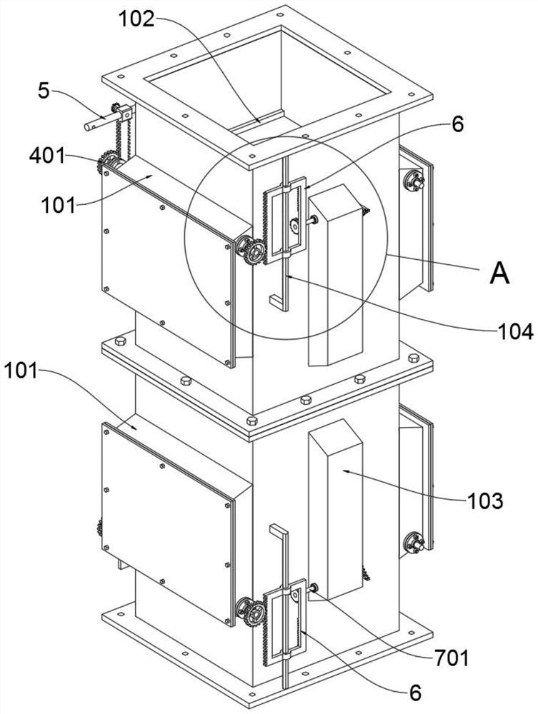
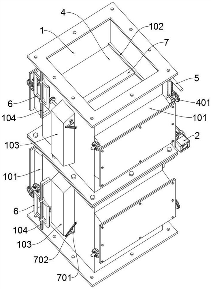
[0039] see Figures 1 to 11 , a double-layer double-door electric flap valve according to a preferred embodiment of the present invention includes a square tube housing 1, and the square tube housing 1 includes a square mounting cover 101, abutting rod 102, a long rectangular cover 103 and a hexagonal positioning cover The shaft 104, the upper and lower prescription tube shells 1 are symmetrically locked together to form the main body support frame of the flap valve, and the left and right side walls of the two prescription tube shells 1 are symmetrically convexly welded with two square installation covers 101 , a cover plate is locked and blocked on the outer openings of the two square installation covers 101 . The middle positions of the rear side walls of the two prescription tube shells 1 are both convexly welded with a long rectangular cover 103, and a transverse beam plate 7 is installed inside the two long rectangular covers 103, and two squares are installed. Inside t...

Embodiment 2

[0042] Further, the cross beam plate 7 includes a rotating shaft 701 and a swing plate 702, a rotating shaft 701 is welded and fixed at the rear ends of the two cross beam plates 7, and the left ends of the two rotating shafts 701 are both sheathed with a pinion, and the two A swinging plate 702 is welded to the right end of the rotating shaft 701, and two tension springs are rotatably supported between the two swinging plates 702 and the rear side walls of the two prescription tube shells 1. The two cross-beam plates 7 are pulled and kept in a horizontally supported abutting state, and when the flip valve is in the open state, the two cross-beam plates 7 can be rotated and placed in a sagging state, and the two prescription tube shells 1 The middle channel is completely vacated to avoid the blocking and blocking of the suctioned materials in the channel caused by the long-term standing of the two transverse beam plates 7 in the transverse support state, so that the materials a...

Embodiment 3

[0046] The working principle of the double-layer double-door electric flap valve according to a preferred embodiment of the present invention is as follows: when switching the open and closed states of the two sets of flaps 4, the initial state of the upper two flaps 4 should be rotated to The drooping position; the connecting rod 201, the T-shaped driving frame 5, the mountain-shaped driving frame 3 and the piston rod of the oil cylinder 2 together form a double-link slider mechanism, through which the piston rod of the oil cylinder 2 can slide forward and backward to push the T The shaped drive frame 5 and the zigzag drive frame 3 slide toward each other, and synchronously control the flipping, opening and closing of the upper and lower two sets of flaps 4. The two drive rods 501 can slide toward each other along the horizontal support shaft at the top of the T-shaped drive frame 5. The outer sides of the two driven gears 401 make the two rows of tooth slots on the inner side...


PUM


Abstract

The invention discloses a double-layer double-door electric flap valve, which comprises a square tube shell, the square tube shell includes a square installation cover, a support rod, a long rectangular cover and a hexagonal positioning shaft, and two square tube shells on the upper and lower sides. Symmetrically locked together to form the main support frame of the flap valve, and the left and right side walls of the two square tube shells are symmetrically welded with two square installation covers, and the outer openings of the two square installation covers are There is a cover plate for locking and sealing; a long rectangular cover is protrudingly welded in the middle of the rear side walls of the two prescription tube shells, and a cross beam plate is installed inside the two long rectangular covers, and The insides of the two square installation covers are all inserted with a flap; the left and right inner walls of the two prescription tube shells are symmetrically welded with two supporting rods. The clamping grooves on the four supporting rods and the two cross-beam plates of the present invention can keep the bottom surface flat when the four supporting rods and the two cross-beam plates are clamped and combined, thereby ensuring the sealing performance of the four flaps when they are closed.

Description

technical field [0001] The invention relates to the technical field of electric flap valves, in particular to a double-layer double-door electric flap valve. Background technique [0002] The flap valve is used as the ash hopper unloading device of various removal equipment and the feeding and unloading device of various mills, dryers, silos and other equipment to prevent wild wind from blowing in. main driving force. The valve plate of the flap valve is automatically opened under the action of the material gravity. After the material falls, the counterweight lever system automatically resets the valve plate to prevent wild wind from blowing in, thereby completing the material transportation. There are mainly single- and double-door flap valves. The double-layer flap valve mainly uses the upper and lower valves to switch at different times so that there is always a layer of valve plate in the middle of the equipment in a closed state to prevent air channeling. [0003] Dou...

Claims


Application Information

Patent Timeline
Patent Type & Authority Patents(China)
IPC IPC(8): F16K1/20F16K1/32F16K1/36F16K1/42F16K27/02F16K31/163F16K31/54
CPCF16K1/2021F16K1/32F16K1/36F16K1/42F16K31/1635F16K31/54F16K27/0227
Inventor 郑坚平蓝林根
Owner ZHEJIANG HONGFENG MASCH EQUIP CO LTD
Learn More