Industrial rare earth treatment discharged sewage purification and filtration treatment device
A sewage purification and treatment device technology, applied in the direction of filtration treatment, special treatment targets, multi-stage water treatment, etc., can solve the problems of high consumption cost, large floor area, etc., and achieve the effect of ensuring the quality of purification
- Summary
- Abstract
- Description
- Claims
- Application Information
AI Technical Summary
Problems solved by technology
Method used
Image
Examples
Embodiment 1
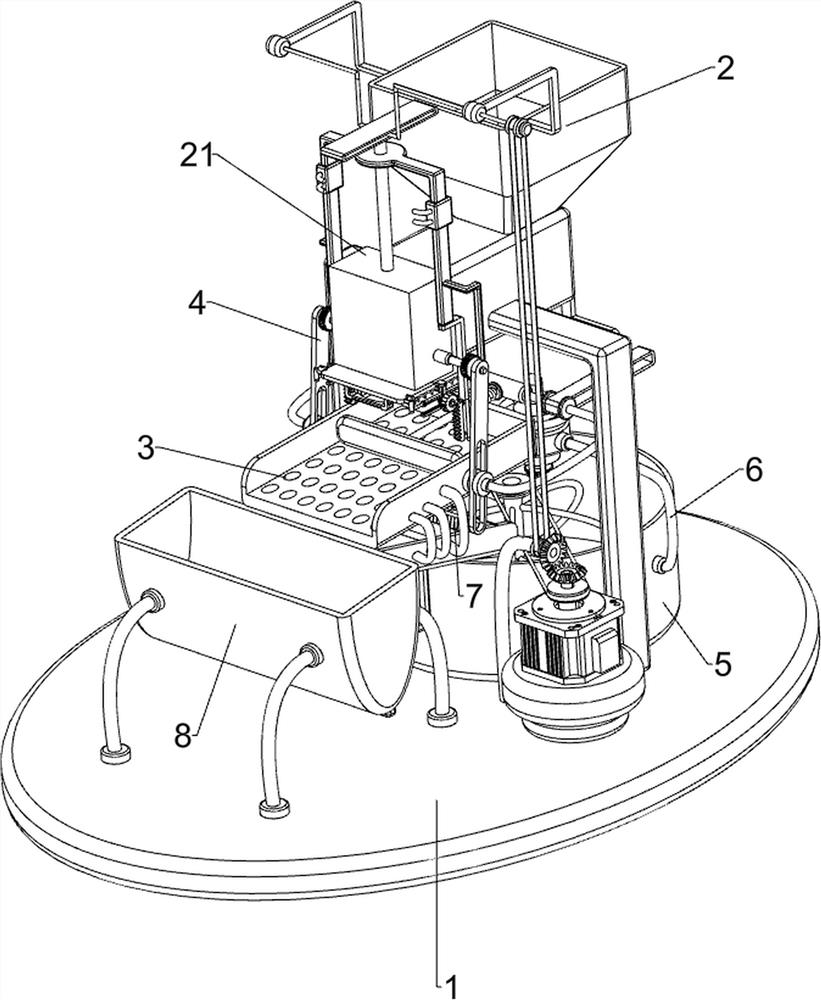
[0046] An industrial rare earth treatment discharge sewage purification and filtration treatment device, such as figure 1 As shown, it includes a base plate 1, a feeding mechanism 2, a pushing mechanism 3 and a solid matter collection frame 8. The rear side of the top of the bottom plate 1 is provided with a feeding mechanism 2, and the feeding mechanism 2 is connected with a pushing mechanism 3. A solid matter collection frame 8 is provided on the side.
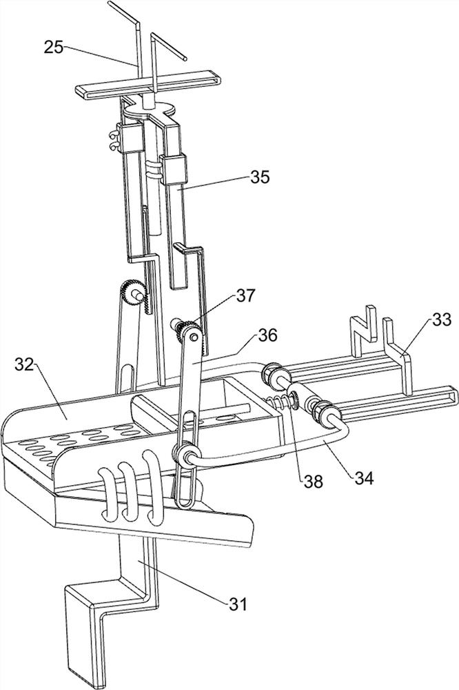
[0047] The staff can put the wastewater into the feeding mechanism 2, start the feeding mechanism 2 to intermittently discharge the wastewater, when the wastewater enters the pushing mechanism 3, automatic solid-liquid separation can be performed, and the liquid will automatically flow backwards, while the feeding mechanism 2 is operating Drive the operation of the pushing mechanism 3 to push the solid forward into the solid material collection frame 8, and after all the processing is completed, the operation of the feeding ...
Embodiment 2
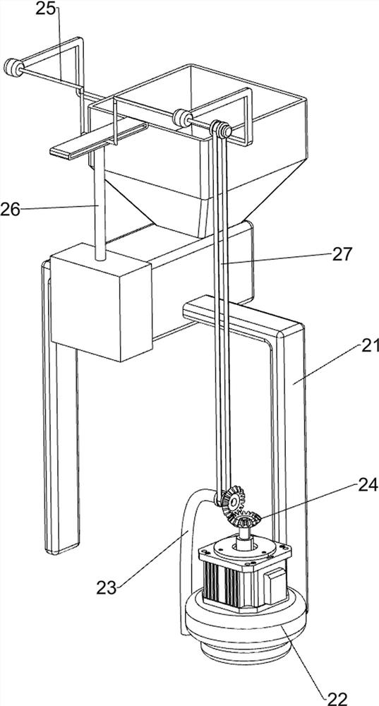
[0049] On the basis of Example 1, such as figure 2 and image 3 As shown, the blanking mechanism 2 includes a blanking rack 21, a motor 22, a support rod 23, a bevel gear set 24, a rotating shaft 25, a lifting block 26 and a first transmission assembly 27, and the rear side of the bottom plate 1 is provided with a blanking rack 21 , the right side of the base plate 1 is provided with a motor 22, the top of the base plate 1 is provided with a support rod 23, the upper part of the support rod 23 is rotatably provided with a shaft sleeve, and a bevel gear group 24 is connected between the shaft sleeve and the output shaft of the motor 22, and the unloading rack 21 front sliding type is provided with lifting block 26, is connected with rotating shaft 25 on the blanking frame 21, and rotating shaft 25 is connected with lifting block 26 upper rotating type, is connected with the first transmission assembly 27 between rotating shaft 25 front ends and the axle sleeve.
[0050] The p...
Embodiment 3
[0053] On the basis of Example 2, such as Figure 4 to Figure 6 As shown, it also includes a closing mechanism 4, the closing mechanism 4 includes a thorn tooth assembly 41, a fixed block 42, a closing plate 43, a rack assembly 44, a second spring 45 and a first handle 46, and the left and right sides of the blanking rack 21 are Connected with a fixed block 42, the outer side of the fixed block 42 and the bottom of the rack bar 35 are connected with a thorn tooth assembly 41, and the front part of the blanking frame 21 is symmetrically slidably provided with a closing plate 43, and the bottom of the closing plate 43 is connected with a first handle 46. A second spring 45 is connected between the left and right sides of the closing plates 43, and a rack assembly 44 is connected between the outer sides of the two closing plates 43 and the transmission shaft of the thorn tooth assembly 41 on the same side.
[0054] The initial closing plates 43 are in the merged state, the rack...
PUM
 Abstract
Description
Claims
Application Information
 - R&D Engineer
- R&D Manager
- IP Professional
- Industry Leading Data Capabilities
- Powerful AI technology
- Patent DNA Extraction
Browse by: Latest US Patents, China's latest patents, Technical Efficacy Thesaurus, Application Domain, Technology Topic, Popular Technical Reports.
© 2024 PatSnap. All rights reserved.Legal|Privacy policy|Modern Slavery Act Transparency Statement|Sitemap|About US| Contact US: help@patsnap.com


