Bicycle seat cushion
A technology for bicycles and seat cushions, applied in the field of bicycles, can solve problems such as being unsuitable for use by cyclists, and achieve the effects of avoiding excessive temperature of seat cushions, increasing applicability, and improving user experience.
- Summary
- Abstract
- Description
- Claims
- Application Information
AI Technical Summary
Problems solved by technology
Method used
Image
Examples
Embodiment 1
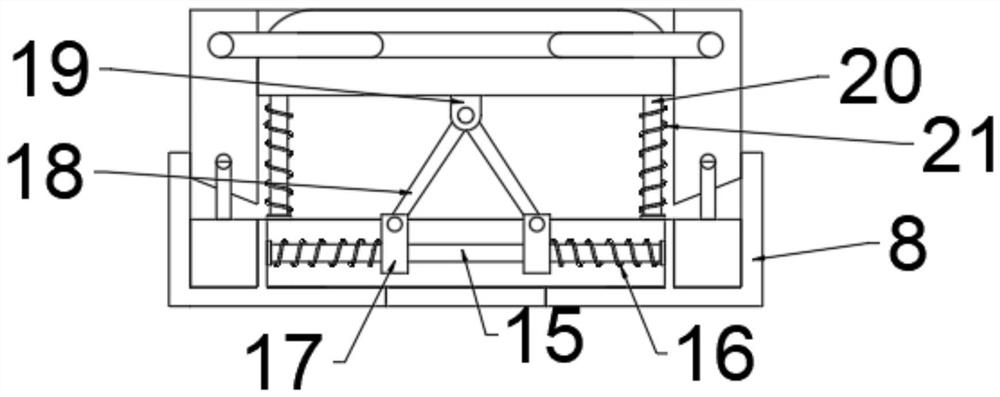
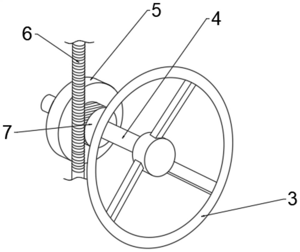
[0027] refer to Figure 1 ~ Figure 3 , a bicycle seat cushion, comprising a car body 1, a support column 2 is connected with a central bolt on the top of the car body 1, an adjustment mechanism is arranged inside the support column 2, and the end of the support column 2 away from the vehicle body 1 is rotatably connected with a cushion box 8. A seat cushion 14 is bolted to the top of the cushion box 8, and the interior of the cushion box 8 is provided with a rainproof mechanism, which includes a hydraulic pipe 9, a first connecting rod 10, a shielding plate 11, and a second connecting rod 12 And the chute 13, the inner left and right ends of the cushion box 8 are bolted to the hydraulic pipe 9, the hydraulic pipe 9 is electrically connected to the outside, the upper part of the hydraulic pipe 9 is bolted to the first connecting rod 10, the first connecting rod 10 The end away from the hydraulic pipe 9 is rotatably connected with a shielding plate 11, and the end of the shieldi...
Embodiment 2
[0034] refer to Figure 4 , a bicycle seat cushion, compared with Embodiment 1, the edge of the support column 2 is provided with an angle adjustment mechanism, and the angle adjustment mechanism includes a fixed plate 22, a sliding cavity 23, a sliding plate 24, a third spring 25, a limiter Position hole 26 and limit column 27, the edge bolt of support column 2 is connected with fixed plate 22, is provided with several limit holes 26 on the fixed plate 22, and limit column 27 is slidingly connected in limit hole 26, limit column 27 Through the lower shell wall of the cushion box 8, the end of the limit post 27 away from the limit hole 26 is bolted to a sliding plate 24, and the inside of the cushion box 8 is provided with a sliding cavity 23, and the sliding plate 24 and the sliding cavity 23 are slidably connected. , the sliding plate 24 is L-shaped, the end of the sliding plate 24 away from the limit post 27 runs through the lower shell wall of the cushion box 8, and the up...
PUM
 Abstract
Description
Claims
Application Information
 - R&D
- Intellectual Property
- Life Sciences
- Materials
- Tech Scout
- Unparalleled Data Quality
- Higher Quality Content
- 60% Fewer Hallucinations
Browse by: Latest US Patents, China's latest patents, Technical Efficacy Thesaurus, Application Domain, Technology Topic, Popular Technical Reports.
© 2025 PatSnap. All rights reserved.Legal|Privacy policy|Modern Slavery Act Transparency Statement|Sitemap|About US| Contact US: help@patsnap.com


