Micro-vibration integrated simulation analysis method of optical remote sensing camera

A technology of optical remote sensing and simulation analysis, applied in the field of integrated simulation of optical remote sensing cameras, can solve the problems of optical-mechanical integration model grids and nodes, low calculation efficiency, etc., achieve strong guiding significance, accurate simulation analysis results, and calculation efficiency Enhanced effect

Active Publication Date: 2021-03-12
CHANGCHUN INST OF OPTICS FINE MECHANICS & PHYSICS CHINESE ACAD OF SCI
View PDF7 Cites 2 Cited by
  • Summary
  • Abstract
  • Description
  • Claims
  • Application Information

AI Technical Summary

Problems solved by technology

[0005] The present invention aims to solve the technical problem that the micro-vibration integration simulation analysis method in the prior art is not only low in calculation efficiency, but also requires fewer grids and nodes of the optical-mechanical integration model in terms of calculation amount, and provides an optical remote sensing camera. Micro-vibration integration simulation analysis method, which is based on the modal information of the optical-mechanical integration model, uses the state space method to obtain the transfer function, and then calculates the LOS value, which can more efficiently and accurately evaluate the optical remote sensing camera under various conditions. Imaging quality when the environment is disturbed

Method used


Image

  • Micro-vibration integrated simulation analysis method of optical remote sensing camera
  • Micro-vibration integrated simulation analysis method of optical remote sensing camera
  • Micro-vibration integrated simulation analysis method of optical remote sensing camera

Examples


Embodiment Construction

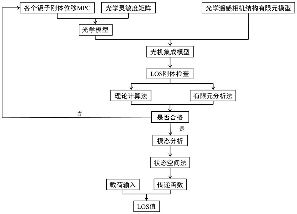
[0055] Such as figure 1 As shown, a micro-vibration integration simulation analysis method for an optical remote sensing camera, the specific process is as follows:

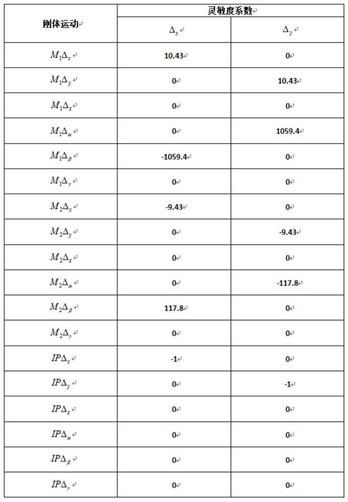
[0056] 1. Establish the finite element model of the optical remote sensing camera structure in MSC.Patran, and use the information such as the radius of curvature of each mirror, the property of the mirror surface material, and the number of the analysis coordinate system to locate the mirror surface of each mirror in the optical software SigFit, and get each mirror by fitting. The rigid body displacement MPC of the mirror is further utilized figure 2 Create an optical model based on the optical sensitivity matrix in , and integrate the optical model into the finite element model in the form of a bdf file to obtain the optical-mechanical integration model of the optical remote sensing camera, see image 3 ;

[0057] 2. Use the theoretical calculation method or the finite element analysis method to perform LOS ...


PUM


Abstract

The invention relates to a micro-vibration integrated simulation analysis method for an optical remote sensing camera. The method mainly comprises the steps of establishing an optical-mechanical integrated model, performing LOS rigid body inspection on the optical-mechanical integrated model, performing modal analysis in a free floating state, obtaining a transfer function by utilizing a state space method, and performing LOS value calculation by utilizing load input and the transfer function, wherein the LOS rigid body inspection is used for verifying the correctness of the establishment of the optical-mechanical integration model; modal analysis is to provide necessary frequency and vibration mode information for a state space method. According to the method, on one hand, the calculationefficiency of a simulation analysis method is very high, on the other hand, optical and mechanical subjects involved in the micro-vibration simulation process of the optical remote sensing camera areintegrated together, and compared with each single-subject idealized model, the coupling influence between different subjects can be comprehensively considered; the real working process of the methodis closer to the real working process of an optical remote sensing camera, and the LOS value obtained through simulation has stronger guiding significance for design of an optical system and evaluation of the imaging performance of the optical system.

Description

technical field [0001] The invention belongs to the field of integrated simulation of optical remote sensing cameras, and in particular relates to a microvibration integrated simulation analysis method of optical remote sensing cameras. Background technique [0002] With the increasing demand for astronomical observation and military and civilian earth observation, optical remote sensing cameras are developing in the direction of large aperture, large field of view and high image quality. In order to ensure that the imaging quality of the camera meets the requirements in the working state, it is necessary to consider the imaging performance of the optical system when the camera is subjected to complex spatial disturbances formed by the vibration source, and micro-vibration simulation analysis is a good means of evaluation and verification . [0003] Optical axis pointing stability (LOS) is an important aspect of optical system image quality evaluation, which directly reflec...

Claims


Application Information

Patent Timeline
Patent Type & Authority Applications(China)
IPC IPC(8): G06F30/23
CPCY02T90/00
Inventor 赵阳李晓波杨勋姜禹希班章
Owner CHANGCHUN INST OF OPTICS FINE MECHANICS & PHYSICS CHINESE ACAD OF SCI
Why Eureka
Try Eureka