Multi-column inlet guide vane/variable stator vane power exponential type combined regulation and control rule design method for multistage axial flow compressor of ship gas turbine

An axial flow compressor, gas turbine technology, applied in mechanical equipment, machine/engine, pump control, etc., can solve the problems of joint control angle law design difficulty, increase in quantity and other problems, achieve engineering design application, reduce resource and time consumption , the effect of simplifying the workload of designers

Active Publication Date: 2021-03-12
中国船舶重工集团公司第七0三研究所
View PDF5 Cites 1 Cited by
  • Summary
  • Abstract
  • Description
  • Claims
  • Application Information

AI Technical Summary

Problems solved by technology

At the same time, with the gradual increase in the number of transduction / stationary vane rows and the increasingly flexible regulation of transduction / stationary vanes, the number of angle combination schemes between multiple transduction / stationary vanes increases sharply, which gives the compressor Multi-column transducible / stationary blade joint control rotation angle design brings greater difficulty and challenge

Method used


Image

  • Multi-column inlet guide vane/variable stator vane power exponential type combined regulation and control rule design method for multistage axial flow compressor of ship gas turbine
  • Multi-column inlet guide vane/variable stator vane power exponential type combined regulation and control rule design method for multistage axial flow compressor of ship gas turbine
  • Multi-column inlet guide vane/variable stator vane power exponential type combined regulation and control rule design method for multistage axial flow compressor of ship gas turbine

Examples


Embodiment Construction

[0037] The present invention is described in more detail below in conjunction with accompanying drawing example:

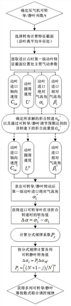
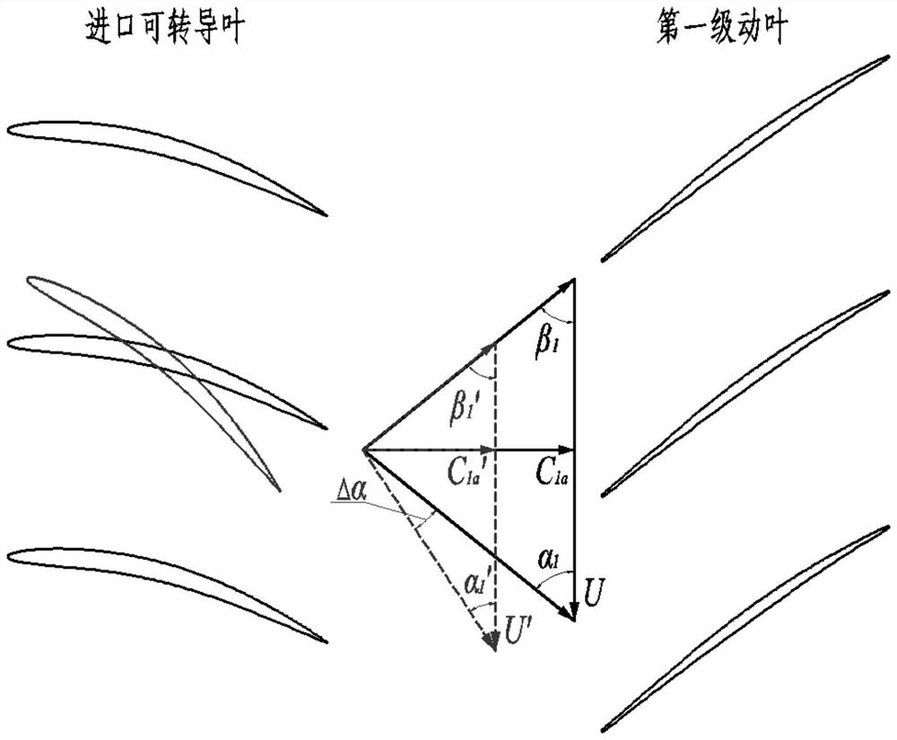
[0038] combine Figure 1-2 , the specific steps of the multi-row transducible / stator blade power exponential joint control law design method for a multi-stage axial flow compressor of a ship gas turbine of the present invention are as follows:

[0039] Step 1: Select the average radius position along the height of the blade as the characteristic cross-section for the calculation of transducible / stator blade rotation angle, and the average radius value can be calculated by arithmetic mean method or area weighted mean method;

[0040] Step 2: Extract the main aerodynamic parameters at the characteristic cross-section position of the first-stage rotor blade at the inlet of the compressor at the design point (at this time, all transducible / stator blade rotation angles are 0°), including: inlet axial velocity C 1a , peripheral speed U, inlet absolute airflow angle α ...


PUM


Abstract

The invention aims to provide a multi-column inlet guide vane / variable stator vane power exponential type combined regulation and control rule design method for a multistage axial flow compressor of aship gas turbine, which comprises the following steps of: extracting aerodynamic parameters at the characteristic section position of a first-stage moving vane of an inlet, and obtaining the aerodynamic parameters of the inlet of the first-stage moving vane at a reduced rotating speed; further, solving the rotating angle of the inlet guide vane at the reduced rotating speed; then enabling the rotation angle of each column of variable stator vanes in the action process to form a power exponential rule relationship with the variable stator vanes, and obtaining a rotation angle value of each column of variable stator vanes; and calculating the rotation angle of each column of inlet guide vanes / variable stator vanes at each characteristic reduced rotation speed to obtain the rotation angle ofeach column of inlet guide vanes / variable stator vanes of the gas compressor at different reduced rotation speeds, thereby designing a multi-column inlet guide vane / variable stator vane power exponential type combined regulation and control rule of the gas compressor. By means of the method, the ideal multi-column inlet guide vane / variable stator vane combined regulation and control corner rule can be rapidly obtained, and the surge margin index of the gas compressor under the low working condition is effectively improved.

Description

technical field [0001] The invention relates to a design method of a gas turbine, in particular to a design method of a ship gas turbine compressor. Background technique [0002] As one of the three most important core components of a marine gas turbine, the compressor's technical performance and reliability directly affect the realization of the safety and economic indicators of a marine gas turbine. The marine gas turbine shall, while ensuring the performance of the design point, pay special attention to the margin and efficient operation under low working conditions. The operating characteristics under such a wide range of variable working conditions make the stability of gas turbines in low working conditions very prominent when they are used as propulsion or power generation in ship power systems, and often become the limiting bottleneck of unit performance, which has great impact on ship gas turbine compressors The performance and stability under non-design conditions...

Claims


Application Information

Patent Timeline
Patent Type & Authority Applications(China)
IPC IPC(8): G06F30/17F04D27/02
CPCG06F30/17F04D27/0246
Inventor 王琦王廷张舟洪青松万新超李冬任兰学
Owner 中国船舶重工集团公司第七0三研究所
Why Eureka
Try Eureka