Non-contact engine blade profile detection device

A non-contact technology for engine blades, applied in mechanical measuring devices, measuring devices, mechanical devices, etc., can solve the problems of high clamping and positioning requirements, low detection repeatability, low detection efficiency, etc., to reduce design requirements and assembly The effect of clamping requirements, improving detection accuracy, and reducing errors

Active Publication Date: 2021-03-12
CHINA HANGFA SOUTH IND CO LTD
View PDF14 Cites 0 Cited by
  • Summary
  • Abstract
  • Description
  • Claims
  • Application Information

AI Technical Summary

Problems solved by technology

[0003] The invention provides a non-contact engine blade profile detection device to solve the technical problems of low detection efficiency of the existing detection method of the engine blade profile, high requirements for clamping and positioning, low detection repeatability and poor compatibility

Method used


Image

  • Non-contact engine blade profile detection device
  • Non-contact engine blade profile detection device
  • Non-contact engine blade profile detection device

Examples


Embodiment Construction

[0033] It should be noted that the features in the embodiments and embodiments in the present application may be combined with each other in the case of an unable conflict. The present invention will be described in detail below with reference to the drawings.

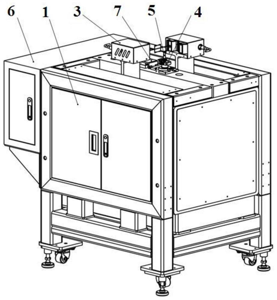
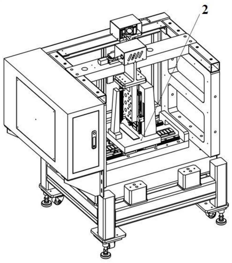
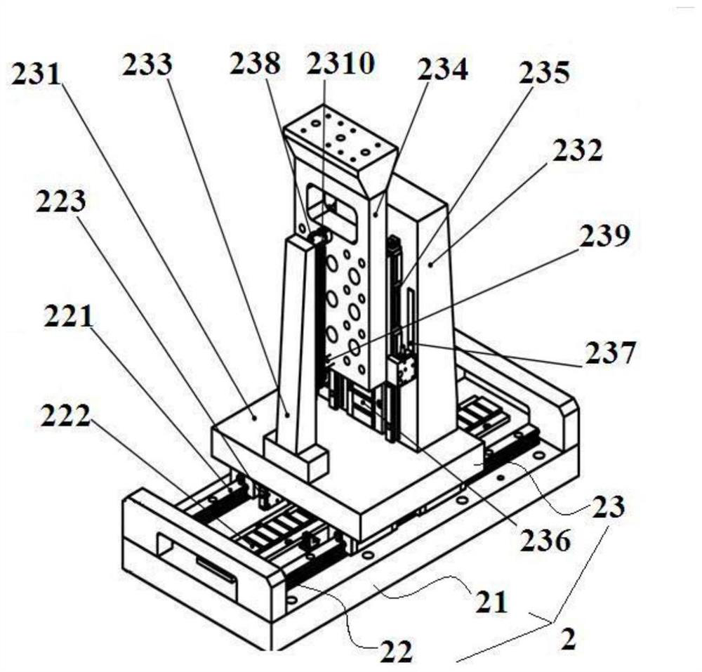
[0034] figure 1 It is a schematic diagram of a non-contact engine blade blade detecting device according to a preferred embodiment of the present invention; figure 2 It is an inside of the non-contact engine blade blade detecting device of a preferred embodiment of the present invention; image 3 It is a schematic diagram of an XZ mobile platform in the preferred embodiment of the present invention; Figure 4 It is a schematic diagram of a wire laser detection component of a preferred embodiment of the present invention; Figure 5 It is a schematic diagram of a clamp of a preferred embodiment of the present invention; Figure 6 It is a connection diagram of a plurality of clamping slide 42 and a fixing macout block 43 o...


PUM


Abstract

The invention discloses a non-contact engine blade profile detection device which comprises a rack body and an XZ moving platform which is arranged in the rack body and used for controlling a laser detection assembly to move by a distance in the X-axis direction and the Z-axis direction respectively, a linear laser detection assembly supported against the top of the XZ moving platform and used forcarrying out non-contact data acquisition on the to-be-detected blade, a clamp used for clamping and fixing the blade root part of the to-be-detected blade, a clamp positioning assembly arranged at the top of the rack body and used for detecting and adjusting the installation and positioning of the clamp, and an electric control cabinet arranged on the rack body and electrically connected with the XZ moving platform, the line laser detection assembly and the clamp positioning assembly. According to the non-contact type engine blade profile detection device, the line laser detection assembly is used for collecting and is not in substantive contact with the to-be-detected blade profile, influence of the measuring head on the posture of the to-be-detected blade profile in contact type detection is avoided, and more original data are obtained in a line-to-surface data collection mode.

Description

Technical field [0001] The present invention relates to the field of engine blade blades, in particular, to a non-contact engine blade blade detecting device. Background technique [0002] The blade is one of the important components of the engine, and the quality of the blade directly affects the performance, life and safety of the engine. Due to the complex blade structure, the processing and manufacturing is difficult, the design indicators are not easy to guarantee. Effectively control the quality of the blade processing, requires a large number of measurements for the blade type, thereby presented a higher requirement for the detection efficiency of the blade surface. Currently, in the air engine blade surface test, the contact type three-coordinate measuring machine is used for measurement. Due to the constraints of the hardware structure and measurement principle of the contact three-coordinate measuring machine, the measurement speed cannot be too fast, and the measuremen...

Claims


Application Information

Patent Timeline
IPC IPC(8): G01B11/24
CPCG01B11/24G01B5/003Y02P70/50
Inventor 郑琪龙智张天辉许美煜高军妮
Owner CHINA HANGFA SOUTH IND CO LTD
Why Eureka
Try Eureka