


Quick Research
Generate reliable direction feasibility study reports for your R&D in just a few steps.

Technical Q&A
Discover and master advanced knowledge NOW. Basics, ideas, possibilities, all at once.

Find Solutions
As an expert in R&D theories, this can generate solutions to your technical problems instantly.

Evaluate Feasibility
Analyze your overall solution with one click, know your potential R&D risks in advance.

Monitor Landscape
Get weekly tech updates, stay abreast of the latest tech innovations and key insights.
A kind of air purification device applied in laboratory
An air purification device and laboratory technology, applied in the application, pipeline arrangement, household heating and other directions, can solve the problems of the purification device moving, unable to purify the air, and the purification is not comprehensive enough, so as to achieve convenient installation, increase friction, and facilitate the The effect of disassembly and replacement
- Summary
- Abstract
- Description
- Claims
- Application Information
AI Technical Summary
Problems solved by technology
Method used
Image

Examples
Embodiment 1
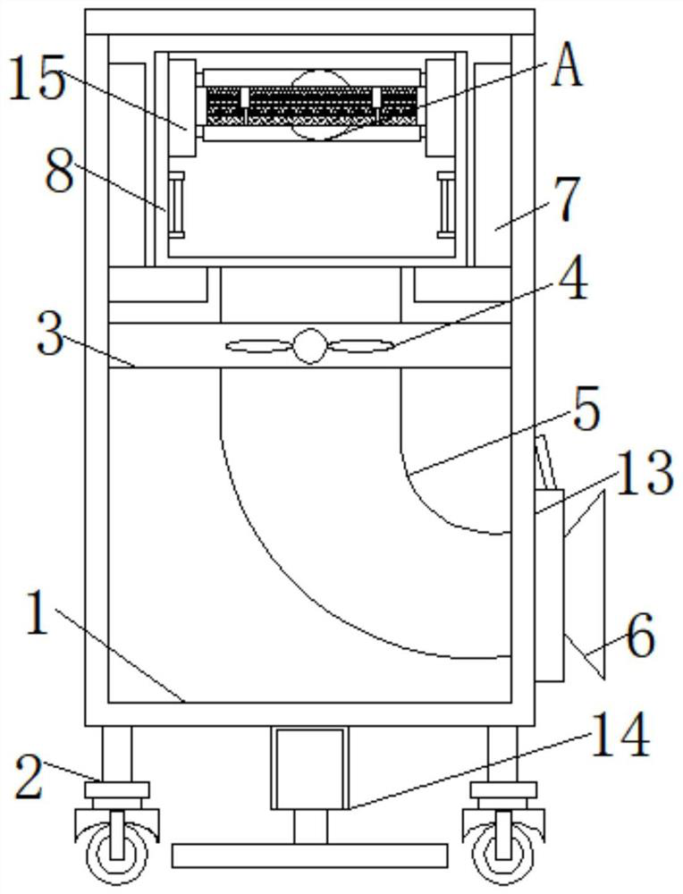
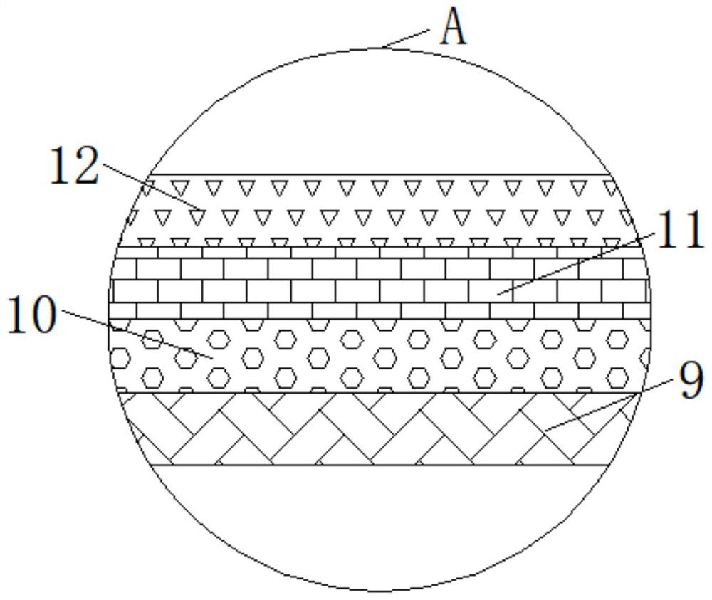
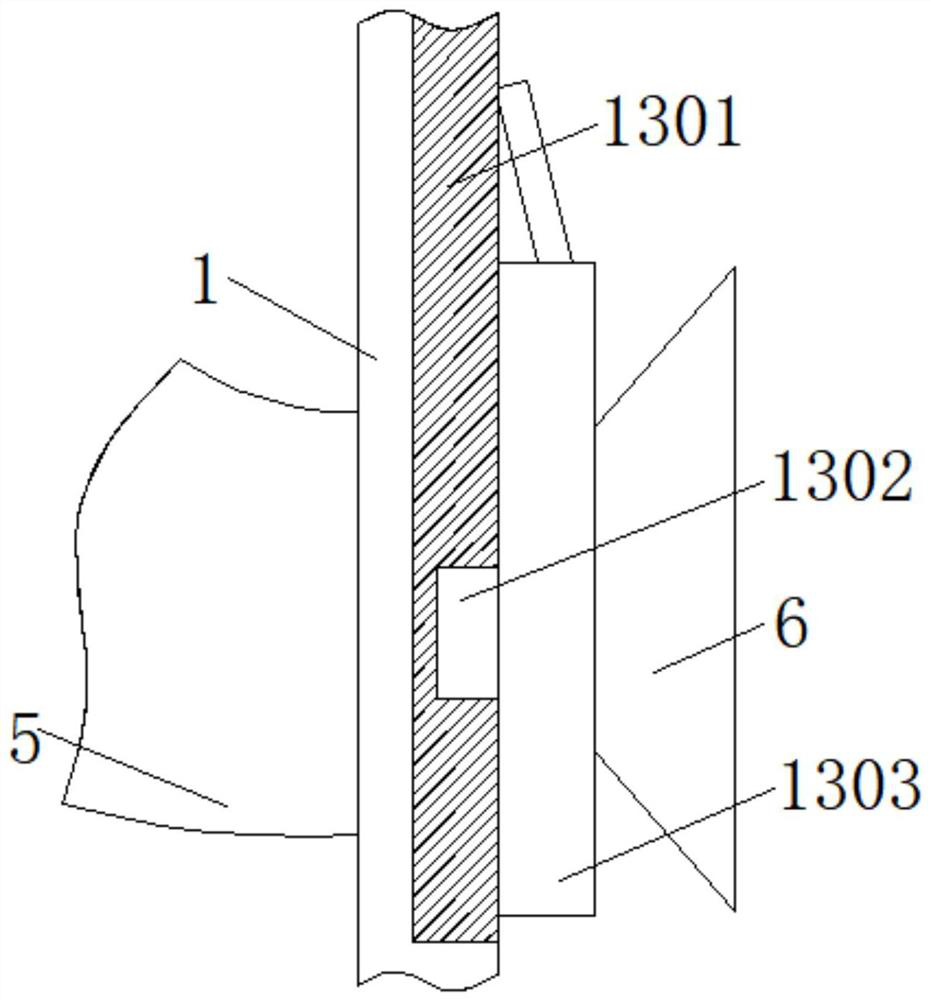
[0028] like Figure 1-Figure 6 As shown, the present invention provides an air purification device for use in a laboratory, comprising: a box body 1, and a plurality of pulleys 2 are installed at the bottom end of the box body 1; A fan 4 is installed inside the plate 3; a spring tube 5 is installed at the bottom end of the partition plate 3, and the spring tube 5 is installed with a draft hood 6 through the box 1, and L is installed on both sides of the inner wall of the box 1. The top of the L-shaped plate 7 is connected with a box body 8, and the inside of the box body 8 is connected with a filter layer 9; the top of the filter layer 9 is connected with an activated carbon layer 10, and the top of the activated carbon layer 10 is connected with There is a deodorizing layer 11; the top end of the deodorizing layer 11 is connected with an aroma storage layer 12, and a regulating mechanism 13 is installed on one side of the box body 1; a limiting mechanism 14 is installed at th...
Embodiment 2
[0035] like Figure 5 As shown, this embodiment provides an air purification device for use in a laboratory. The difference from Embodiment 1 is that the interior of the limiting mechanism 14 includes a sleeve 1401; the sleeve 1401 is connected to the bottom of the box 1 The ends are fixedly connected, and the inner top of the sleeve 1401 is installed with two first limiting grooves 1402; the two sides of the inner wall of the sleeve 1401 are respectively fixedly connected with first clamping grooves 1403, and the inner parts of the first clamping grooves 1403 are engaged with each other. A first blocking block 1404 is connected; a support rod 1405 is fixedly connected to the top of the first blocking block 1404, and a first limit block 1406 is connected to the top of the support rod 1405; the first limit block 1406 is connected to the first limit block 1406. The interior of the position slot 1402 is in a snap connection, and a pressing rod 1407 is fixedly connected to one side ...
Embodiment 3
[0041] like Image 6 As shown, this embodiment provides an air purification device for use in a laboratory. The difference from Embodiment 2 is that the interior of the clamping mechanism 15 includes two disinfection lamps 1501; the disinfection lamps 1501 and the box body 8 Two second card slots 1502 are respectively installed on both sides of the inner wall of the box body 8; the inner parts of the second card slots 1502 are connected with two second locking blocks 1503, and the second locking blocks 1503 A second return spring 1504 is fixedly connected to the top of the second block 1503; a limit plate 1505 is connected to one side of the second block 1503, and the limit plate 1505 is connected to the bottom end of the filter layer 9; the limit plate 1505 is connected to the incense storage The top ends of the layers 12 are connected, and the bottom ends of the limit plates 1505 are connected with two telescopic rods 1506; the bottom ends of the telescopic rods 1506 are fix...
PUM
 Abstract
Description
Claims
Application Information
 - R&D Engineer
- R&D Manager
- IP Professional
- Industry Leading Data Capabilities
- Powerful AI technology
- Patent DNA Extraction
Browse by: Latest US Patents, China's latest patents, Technical Efficacy Thesaurus, Application Domain, Technology Topic, Popular Technical Reports.
© 2024 PatSnap. All rights reserved.Legal|Privacy policy|Modern Slavery Act Transparency Statement|Sitemap|About US| Contact US: help@patsnap.com