Warning lamp and rotating mechanism thereof

A technology of rotating mechanism and rotating limit, applied in the field of warning lights, can solve the problems of lack of rotation adjustment ability, inconvenient positioning, complex structure and other problems of warning lights, and achieve the effect of improving market competitiveness, simple structure and beautiful appearance.

Pending Publication Date: 2021-03-12
JIANGYIN CHANGJIANG ELECTRIC APPLIANCE
View PDF2 Cites 1 Cited by
  • Summary
  • Abstract
  • Description
  • Claims
  • Application Information

AI Technical Summary

Problems solved by technology

[0002] At present, warning lights are installed on construction machinery and other equipment to warn of its status. In order to meet the adjustment needs, it is now required to have a certain angle rotation adjustment ability; but conventional engineering warning lights lack the ability to rotate and adjust
For this reason, some companies have used the warning rotation ability of ordinary vehicles for reference, such as "a rotatable warning light bracket" disclosed in Chinese patent CN201820899506.4, which has a simple rotation structure, but the positioning after rotation adjustment is not convenient; , there are also companies using "a rotating warning light" as disclosed in Chinese patent CN201821799771.1, but it uses a motor to adjust the rotation, so its structure is complex, the cost is high, and it is prone to failure due to electrical failures in harsh working conditions

Method used


Image

  • Warning lamp and rotating mechanism thereof
  • Warning lamp and rotating mechanism thereof
  • Warning lamp and rotating mechanism thereof

Examples


Embodiment Construction

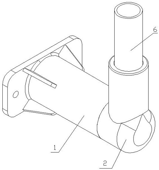
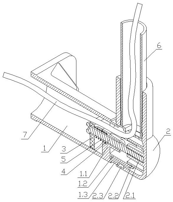
[0026] see Figure 1~8 , a rotating mechanism that the present invention relates to includes a base pipe 1 and a connecting pipe 2 that are plugged and fitted. The nozzle end of the base pipe 1 is provided with a plurality of insertion teeth 1.3, and a nozzle of the connecting pipe 2 The inside of the pipe wall at the end is provided with an insertion groove 2.3 for insertion of the insertion tooth 1.3, and the other nozzle end of the connecting pipe 2 is sealed with a cover, and a stopper 1.1 is installed at the nozzle end of the base pipe 1;

[0027] A limit stopper 3 is slidably arranged in the base tube 1, and one end of the connecting rod 4 is connected with the limit stopper 3, and the other end is connected with the cover of the connecting pipe 2, and the limit stopper 3 and the stopper 1. An elastic member 5 is arranged between them;

[0028] Further, the inner surface of the cover of the connecting pipe 2 is provided with a connecting column 2.1, and the connecting c...


PUM


Abstract

The invention relates to a warning lamp and the rotating mechanism thereof. The warning lamp comprise a base pipe (1) and a connecting pipe (2) which are matched in an inserted mode, wherein a plurality of inserted connection teeth (1.3) are arranged at the pipe opening end of the base pipe (1), inserted connection grooves (2.3) allowing the inserted connection teeth (1.3) to be inserted therein are formed in the pipe wall of one pipe opening end of the connecting pipe (2), and the other pipe opening end of the connecting pipe (2) is sealed with a sealing cover; a stop block (1.1) is mounted at the end part of a pipe orifice of the base pipe (1); a limiting stop block (3) is arranged in the base pipe (1) in a sliding mode, one end of the connecting rod (4) is connected with the limiting stop block (3), the other end of the connecting rod (4) is connected with a sealing cover of the connecting pipe (2), and an elastic piece (5) is arranged between the limiting stop block (3) and the stop block (1.1). According to the warning lamp, a mechanical adjusting mode is adopted, rotating adjustment and positioning are very convenient, the structure is simple, manufacturing cost is low, and market competitiveness of products can be improved.

Description

technical field [0001] The invention relates to a warning light, in particular to a warning light with a rotating function. Background technique [0002] At present, warning lights are installed on construction machinery and other equipment to warn of their status, and they are now required to have a certain angle rotation adjustment ability in order to adjust; but conventional engineering warning lights lack the ability to rotate and adjust. For this reason, some companies have used the warning rotation ability of ordinary vehicles for reference, such as "a rotatable warning light bracket" disclosed in Chinese patent CN201820899506.4, which has a simple rotation structure, but the positioning after rotation adjustment is not convenient; , there are also companies using "a rotating warning light" as disclosed in Chinese patent CN201821799771.1, but it uses a motor to adjust the rotation, so its structure is complex, the cost is high, and it is prone to failure due to electri...

Claims


Application Information

Patent Timeline
Patent Type & Authority Applications(China)
IPC IPC(8): F21S8/00F21V21/26F21V23/06
CPCF21S8/00F21V21/26F21V23/06
Inventor 张卫王超
Owner JIANGYIN CHANGJIANG ELECTRIC APPLIANCE
Why Eureka
Try Eureka