Fabricated type drainage ditch and construction method thereof

A drainage ditch and prefabricated technology, applied to drainage structures, chemical instruments and methods, water supply devices, etc., can solve the problems that two components cannot be assembled horizontally, the cover plate is uneven, and the drainage weir is silted and blocked.

Inactive Publication Date: 2021-03-12
HUBEI PEI HAN CONSTR CO LTD
View PDF6 Cites 1 Cited by
  • Summary
  • Abstract
  • Description
  • Claims
  • Application Information

AI Technical Summary

Problems solved by technology

[0007] The main purpose of the present invention is to provide a prefabricated drainage ditch and its construction method, which solves the phenomenon of unevenness of the cover plate, the accumulation and blockage of the drainage weir in the drainage ditch, and the inability to assemble horizontally between the two components, so the waterproof function is relatively poor. bad question

Method used


Image

  • Fabricated type drainage ditch and construction method thereof
  • Fabricated type drainage ditch and construction method thereof
  • Fabricated type drainage ditch and construction method thereof

Examples


Embodiment 1

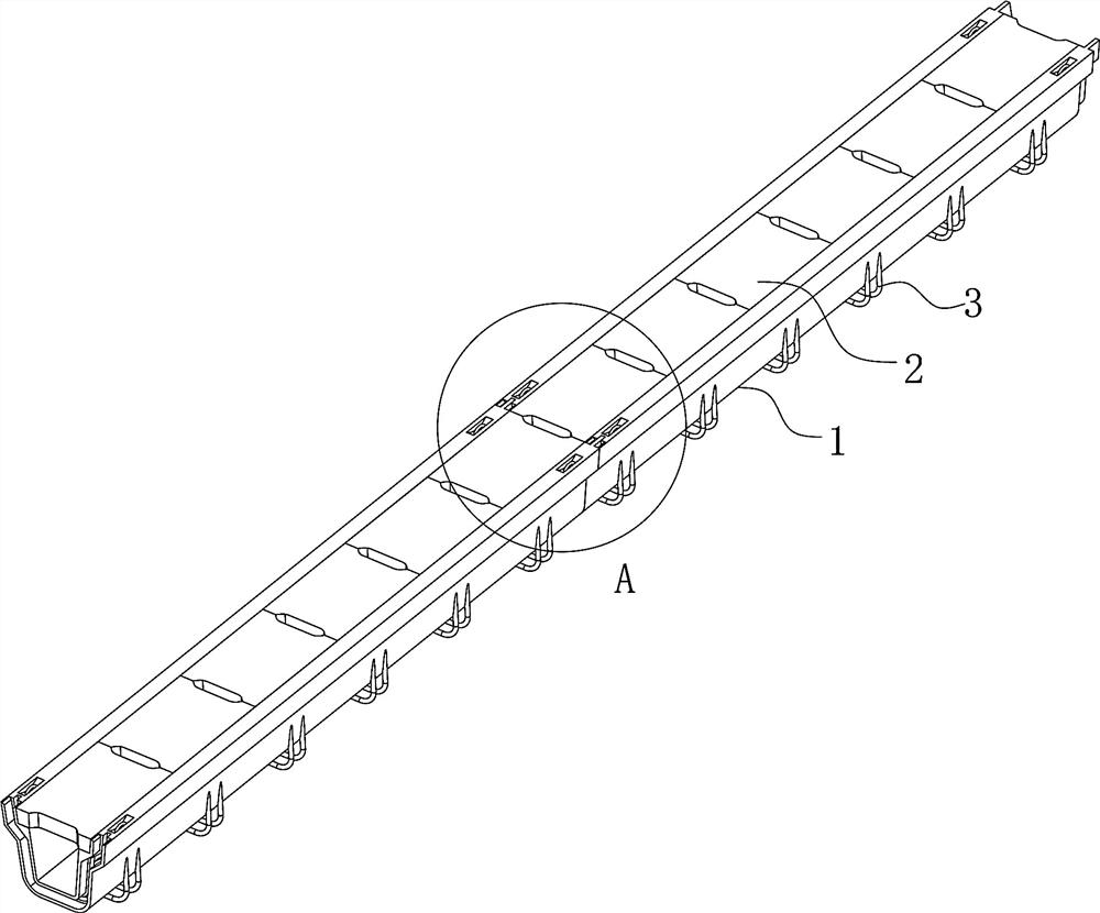
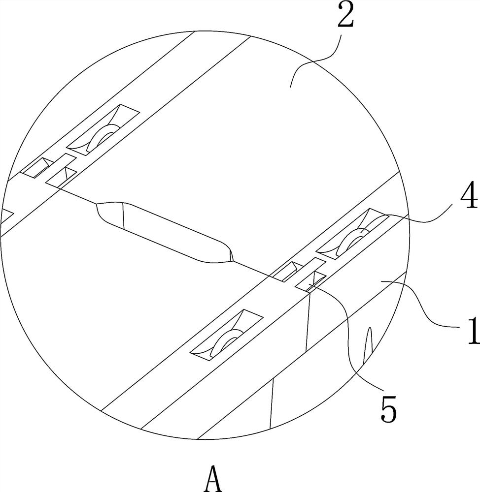
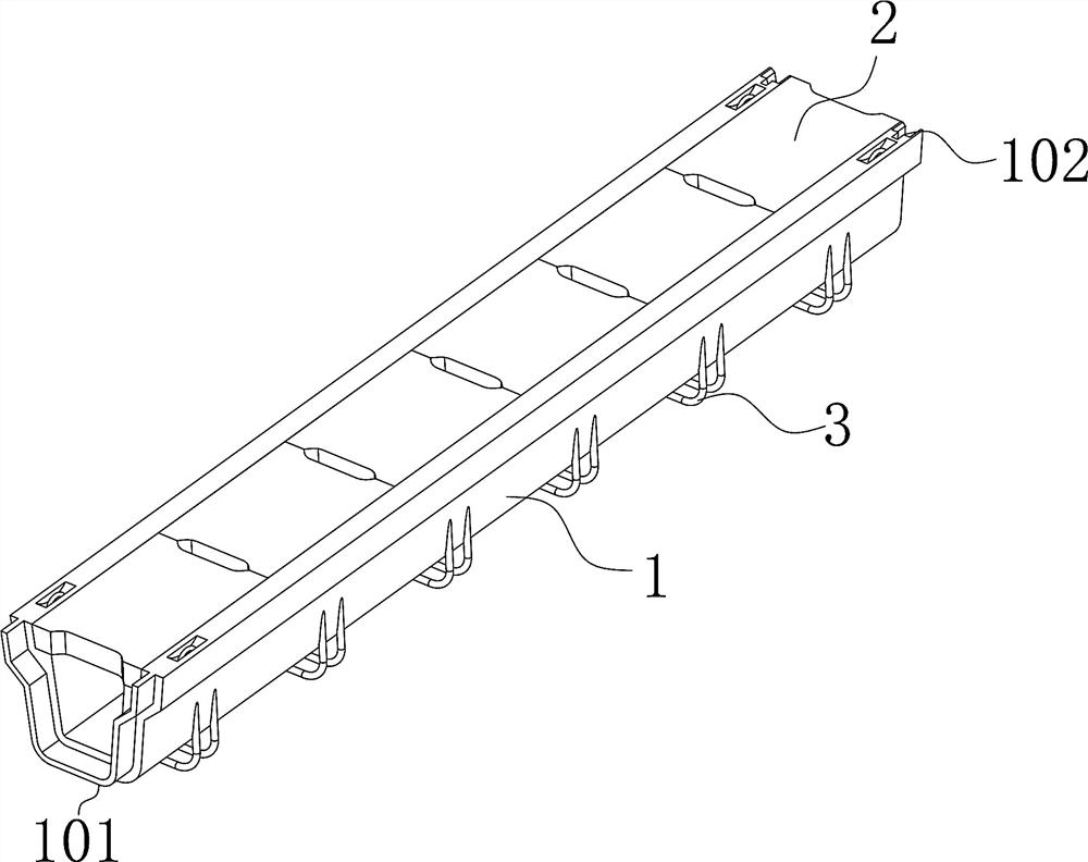
[0045] Such as Figure 1~12As shown, an assembled drainage ditch includes a drainage ditch 1, one end of the drainage ditch 1 is provided with a connecting protrusion 101, and the other end is provided with a mounting groove 102, the connecting protrusion 101 matches the mounting groove 102, and the mounting groove 102 is a A waterproof groove 5 is provided on the side. After the connection protrusion 101 is docked with the installation groove 102, the root of the connection protrusion 101 is set inside the waterproof groove 5, and the waterproof glue 6 is injected into the waterproof groove 5. There are multiple The stabilizing steel bars 3 are in a "U" shape. One end of the drainage ditch 1 is provided with a connection protrusion 101, and the other end is provided with an installation groove 102. Multiple drainage ditches 1 are installed and spliced ​​through the connection protrusion 101 and the installation groove 102. Between the connection protrusion 101 and the install...

Embodiment 2

[0056] Further illustrate in conjunction with embodiment 1, as Figure 1-12 As shown in the structure, the drainage ditch 1, the cover plate 2 and the dredging cover plate 10 are produced in the factory according to the drawings. The steel mesh sheet 9 and the stabilizing steel bar 3 are put into the drainage ditch mold first, and then the cement is poured into the mold to manufacture the drainage ditch 1.

[0057] Excavate and install the groove 8 at the installation place of the drainage ditch, and carry out the base tamping at the bottom of the installation groove 8. If the soil quality is relatively poor, it should be replaced and then compacted.

[0058] During the compaction process, do a good job of slope finding according to the direction of water flow in the gutter to ensure smooth water flow.

[0059] Use the hoisting equipment to hoist the drainage ditch 1 into the installation groove 8 , and splice the connecting protrusion 101 and the installation groove 102 of e...


PUM


Abstract

The invention provides a fabricated type drainage ditch. The fabricated type drainage ditch comprises a drainage ditch body; a connecting protruding head is arranged at one end of the drainage ditch body; an installation groove is formed in the other end of the drainage ditch body; the connecting protruding head is matched with the installation groove; a waterproof groove is formed in one side ofthe installation groove; after the connecting protruding head is in butt joint with the installation groove, the root of the connecting protruding head is arranged in the waterproof groove; waterproofglue is injected into the waterproof groove; and a plurality of stabilizing reinforcing steel bars are arranged at the bottom of the drainage ditch body and are of a U-shaped structure. Multiple drainage ditch bodies are installed and spliced through connecting protruding heads and installation grooves, the waterproof glue is injected into waterproof grooves between the connecting protruding heads and the installation grooves, the waterproof glue is solidified, the situation that water does not leak from the drainage ditch bodies is guaranteed, the waterproof effect is good, and the splicingspeed is high.

Description

technical field [0001] The invention relates to the field of drains, in particular to an assembled drain and a construction method thereof. Background technique [0002] The main function of the construction site drainage ditch is to drain the rainwater, domestic water and production water out of the construction site in an organized manner to ensure that there is no water accumulation within the construction site. However, conventional temporary drainage ditches are mainly composed of brick masonry and reinforced concrete prefabricated panels or reinforced water grates, and the inside of the brick masonry also needs to be waterproofed and plastered, which greatly increases the labor cost and labor cost of the temporary construction project. The cost of materials cannot be recycled, which is not conducive to environmental protection, and the construction period is long. The traditional drainage ditch is generally separated from the ditch body and the cover plate. The cover ...

Claims


Application Information

Patent Timeline
Patent Type & Authority Applications(China)
IPC IPC(8): E03F5/04E03F5/06E03F3/04E03F3/06E03F5/14
CPCE03F5/0404E03F5/06E03F3/04E03F3/06E03F3/046
Inventor 覃发科何滔孙静静张登辉
Owner HUBEI PEI HAN CONSTR CO LTD
Why Eureka
Try Eureka