
Automatic mesh belt correcting device

An automatic deviation correction device and correction technology, applied in the direction of conveyor control devices, transportation and packaging, conveyor objects, etc., can solve the problems of increasing labor intensity, time-consuming and labor-intensive work, etc., to achieve the elimination of manual intervention, improve operating efficiency, Guarantee the effect of long-term reliable operation

Active Publication Date: 2021-03-12
HENGLI ELETEK
View PDF7 Cites 0 Cited by
  • Summary
  • Abstract
  • Description
  • Claims
  • Application Information

AI Technical Summary

Problems solved by technology

[0005] The invention provides an automatic deviation correction device for the mesh belt, which solves the problem of manual intervention for sluggishly fixing the mechanical guide wheel, which is time-consuming and labor-intensive, and increases the labor intensity of the staff

Method used


Image

  • Automatic mesh belt correcting device
  • Automatic mesh belt correcting device
  • Automatic mesh belt correcting device

Examples


no. 1 example

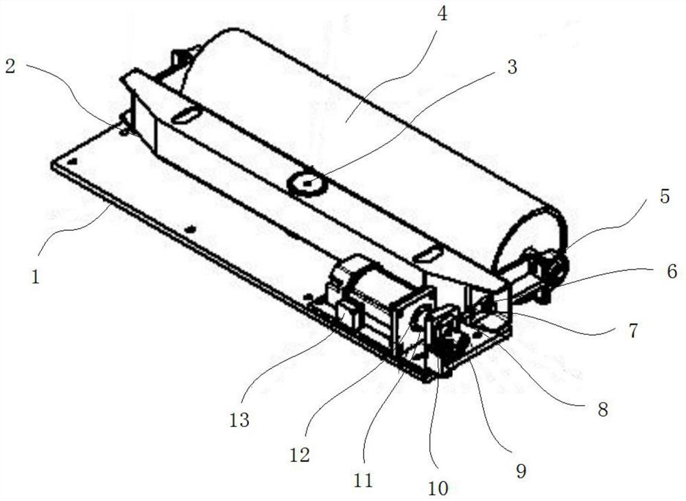
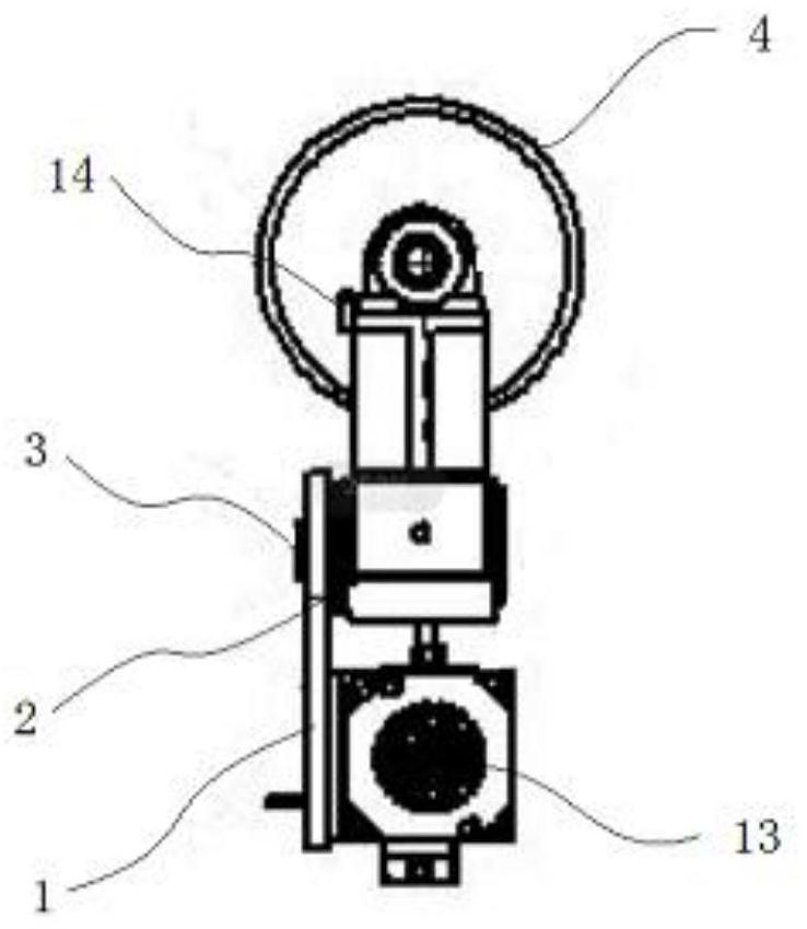
[0033] Please refer to figure 1 , figure 2 ,in, figure 1 A schematic structural view of the first embodiment of the mesh belt automatic deviation correction device provided by the present invention; figure 2 for figure 1 The side view of the mesh belt automatic deviation correction device shown. The mesh belt automatic correction device includes:

[0034] Correction bottom plate 1;

[0035] A deviation correction installation plate 2, the deviation correction installation plate 2 is arranged on the top of the deviation correction bottom plate 1, and a rotation shaft 3 is arranged on the deviation correction installation plate 2;

[0036] The deviation correction wheel 4 is arranged on one side of the deviation correction base plate 1, and the axis center of the deviation correction wheel 4 is provided with a seated bearing 5, and one side of the belt seat bearing 5 is provided with a connecting bearing 6, and the connecting bearing 6 The axis is provided with a connect...

no. 2 example

[0054] Please refer to Figure 3-5 , based on the mesh belt automatic deviation correction device provided in the first embodiment of the present application, the second embodiment of the present application proposes another mesh belt automatic deviation correction device. The second embodiment is only a preferred mode of the first embodiment, and the implementation of the second embodiment will not affect the independent implementation of the first embodiment.

[0055] Specifically, the difference of the mesh belt automatic deviation correction device provided by the second embodiment of the present application is that it also includes a movable frame 15, and a screw rod 16 is rotatably connected between the two sides of the inner wall of the movable frame 15, and the The outer surface of the screw rod 16 is threadedly connected with a threaded block 17, one end of the screw rod 16 passes through the movable frame 15 and extends to the outside of the movable frame 15, and the...


PUM


Abstract

The invention provides an automatic mesh belt correcting device which comprises a correcting bottom plate and a correcting mounting plate, wherein the correcting mounting plate is arranged on the topof the correcting bottom plate, and a rotating shaft is arranged on the correcting mounting plate; a correcting wheel is arranged on one side of the correcting bottom plate, a bearing with a pedestalis arranged at the axis of the correcting wheel, and a connecting bearing is arranged on one side of the bearing with the pedestal. The automatic mesh belt correcting device drives a motor to rotate to drive a crankshaft to operate to be linked with a moving connecting block, a pulling connecting guide bar and a connecting bearing to move linearly, and meanwhile, to drive the correcting mounting plate to rotate at a certain angle around the rotating shaft and to feed back to a photoelectric switch. When the photoelectric switch is of no signal, i.e. the mesh belt correction is adjusted, a purpose of correcting the mesh belt is finally achieved. Online operation detection and real-time correction of the mesh belt are achieved, and manual intervention is removed, so that long-term reliable operation of the device is ensured and the operation efficiency is improved greatly.

Description

technical field [0001] The invention relates to the field of mesh belt type continuous operation equipment, in particular to a mesh belt automatic deviation correction device. Background technique [0002] Mesh belt conveying equipment is a material handling machine that continuously conveys materials on a certain line, also known as a continuous conveyor, which can be divided into mesh belt type and mesh chain type. The conveyor can carry out horizontal, inclined and vertical conveying, and can also form a space conveying line. The conveying line is generally fixed, the conveying capacity of the conveyor is large, the conveying distance is long, and several process operations can be completed at the same time during the conveying process, so the application is very Widely used in all walks of life. [0003] The continuous high-temperature heat treatment mesh belt furnace equipment is a kind of horizontal continuous operation equipment. The overall length of the equipment i...

Claims


Application Information

Patent Timeline
IPC IPC(8): B65G15/64B65G43/00B65G39/16
CPCB65G15/64B65G43/00B65G39/16
Inventor 高文杜润生王育蔡传辉
Owner HENGLI ELETEK
Learn More