Eureka AIR delivers breakthrough ideas for toughest innovation challenges, trusted by R&D personnel around the world.

Machining engraving equipment

A technology of engraving equipment and machining, applied in metal processing equipment, metal processing machine parts, manufacturing tools, etc., can solve problems such as health effects, hinder the formability of works, affect aesthetics, etc., to enhance work efficiency and increase image clarity degree, the effect of reducing the degree of inclination

Active Publication Date: 2021-03-12
NANJING AUDIT UNIV
View PDF7 Cites 2 Cited by
  • Summary
  • Abstract
  • Description
  • Claims
  • Application Information

AI Technical Summary

Problems solved by technology

[0003] However, when the existing low-power engraving machines are engraving, the engraving needs to be more precise. For the flatness of the ground, the dust during engraving needs to be controlled in time. If the engraving machine is placed on the uneven ground, the The carved finished product will be inclined, which will affect its aesthetics, and the dust during the carving process will have a health impact on the environment in which the operator lives, and hinder the shaping of the work during the carving process

Method used


Image

  • Machining engraving equipment
  • Machining engraving equipment
  • Machining engraving equipment

Examples


Embodiment 1

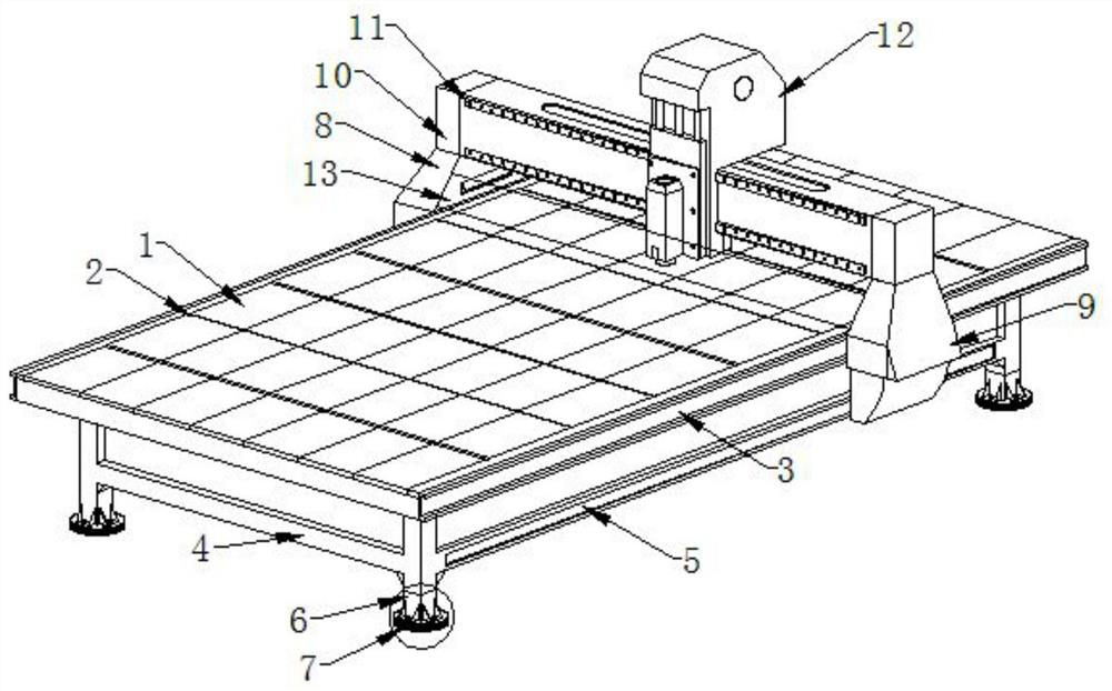
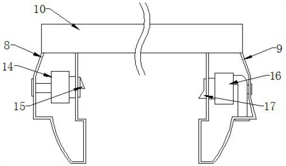
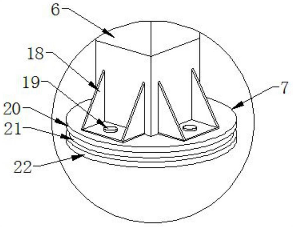
[0023] Such as Figure 1-4 As shown, the present invention provides a kind of machining engraving equipment, including a panel 1, the surface of the panel 1 is provided with a groove 2, and the groove 2 is arranged in a horizontal shape, and the two ends of the panel 1 are installed with a first slide Slot 3, the bottom end of the panel 1 is equipped with a bracket 4, the two sides of the bracket 4 are provided with a second chute 5, the four corners of the bracket 4 are provided with feet 6, and the bottom of the feet 6 is installed There is a base 7, a left side slider 8 is installed on one side of the panel 1, a right side slider 9 is installed on the other side of the panel 1, and a beam 10 is installed on the top of the left side slider 8, so A side surface of the crossbeam 10 is provided with a slide rail 11, the middle part of the crossbeam 10 is provided with an engraving host 12, and a dust-proof strip 13 is installed between the left side slider 8 and the right side ...


PUM


Abstract

The invention discloses machining engraving equipment. The machining engraving equipment comprises a panel, a groove is transversely formed in the surface of the panel, first sliding grooves are formed in the two ends of the panel, a support is installed at the bottom end of the panel, second sliding grooves are formed in the surfaces of the two sides of the support, supporting legs are arranged at the four corners of the support, and a base is installed at the bottom ends of the supporting legs. A left sliding block is installed on one side of the panel, a right sliding block is installed onthe other side of the panel, a cross beam is installed at the top end of the left sliding block, a sliding rail is arranged on the surface of one side of the cross beam, an engraving main machine is installed in the middle of the cross beam, a dustproof strip is installed between the left sliding block and the right sliding block, and an air blower is installed in the left sliding block. By arranging a dust removing structure, the engraving machine can remove dust in time in the engraving process, the dust raising environment in the engraving process is reduced, the image clarity degree in theengraving process is increased, and the effects of improving the working efficiency and improving the working environment are achieved.

Description

technical field [0001] The invention relates to the field of engraving processing, in particular to a mechanical processing engraving equipment. Background technique [0002] Engraving is a combination of drilling and milling in terms of processing principle, and the various data input modes of the engraving machine can be easily used according to the needs. There are two types of computer engraving machines: laser engraving and mechanical engraving, both of which are divided into high-power and low-power. Because the engraving machine has a wide range of applications, it is necessary to understand the most suitable application range of various engraving machines. The low-power ones are suitable for double-color boards, architectural models, small signs, three-dimensional crafts, etc., while engraving jade and metal requires power. Above 1500W, a high-power engraving machine can do what a low-power engraving machine does, and is most suitable for large-scale cutting, emboss...

Claims


Application Information

Patent Timeline
Patent Type & Authority Applications(China)
IPC IPC(8): B23Q1/01B23Q11/00
CPCB23Q1/015B23Q11/0046
Inventor 许文瀚齐荻
Owner NANJING AUDIT UNIV
Why Eureka
Eureka Blog
Learn More