
A roller pressing driving mechanism and a laser cleaning machine

A driving mechanism and roller technology, applied in the field of laser cleaning machines, can solve the problems of single cleaning method, low cleaning efficiency, surface damage, etc., and achieve the effect of improving cleaning efficiency, reducing labor intensity and ensuring surface integrity

Active Publication Date: 2022-02-15
深圳水滴激光科技有限公司
View PDF11 Cites 0 Cited by
  • Summary
  • Abstract
  • Description
  • Claims
  • Application Information

AI Technical Summary

Problems solved by technology

The existing laser cleaning machine has a relatively simple cleaning method for cylindrical workpieces. Most of the clamping mechanisms are used to clamp the two ends of the cylindrical workpiece and then rotate directly. It needs manual loading and unloading by technicians, and the cleaning efficiency is low; at the same time The rotating and fixing method of clamping, fixing and rotating will easily cause the surface of the clamped part of the cylindrical workpiece to be damaged, cracked or even deformed, and the cleaned cylindrical workpiece will need to be repaired or even scrapped and cannot be used normally.

Method used


Image

  • A roller pressing driving mechanism and a laser cleaning machine
  • A roller pressing driving mechanism and a laser cleaning machine
  • A roller pressing driving mechanism and a laser cleaning machine

Examples


Embodiment Construction

[0036] Embodiments of the present invention are described in detail below, examples of which are shown in the drawings, wherein the same or similar reference numerals designate the same or similar elements or elements having the same or similar functions throughout. The embodiments described below by referring to the figures are exemplary only for explaining the present invention and should not be construed as limiting the present invention.

[0037] In describing the present invention, it should be understood that the terms "center", "longitudinal", "transverse", "length", "width", "thickness", "upper", "lower", "front", " Rear", "Left", "Right", "Vertical", "Horizontal", "Top", "Bottom", "Inner", "Outer", "Axial", "Radial", "Circumferential" The orientation or positional relationship indicated by etc. is based on the orientation or positional relationship shown in the drawings, and is only for the convenience of describing the present invention and simplifying the descriptio...


PUM


Abstract

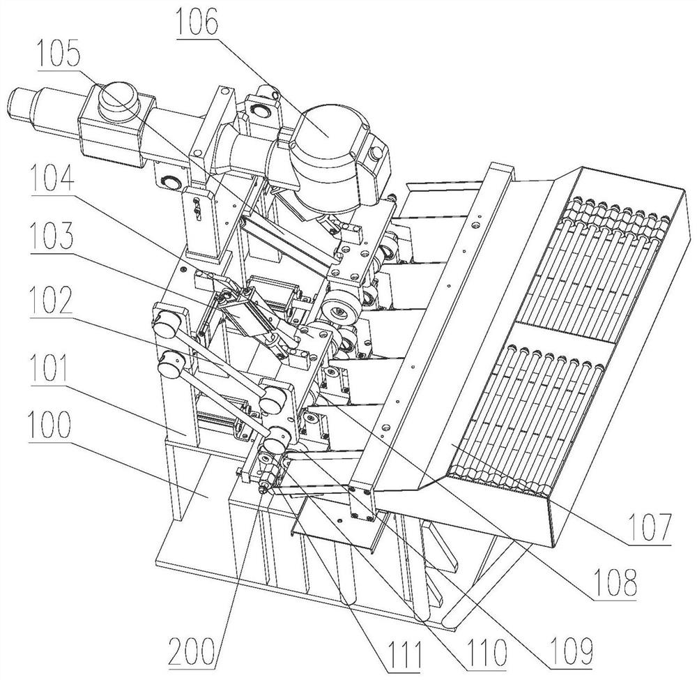
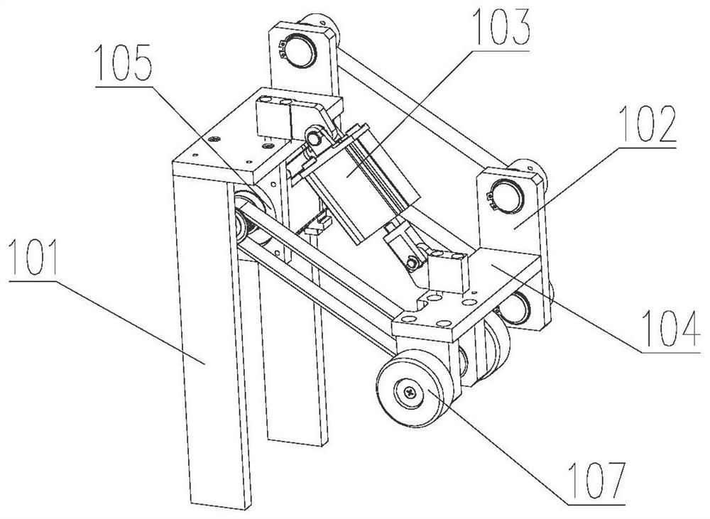
The invention discloses a roller-driven compacting mechanism and a laser cleaning machine, wherein the roller-driven compacting mechanism proposed by the present invention mainly uses rollers to support and rotate a cylindrical workpiece set in a rolling installation position, and then drives it through a driving structure. The roller rotates and the friction drives the workpiece to rotate, so that the rotation and positioning of the workpiece can be realized by means of rotation and compression, which can avoid damage to the workpiece and ensure the surface integrity of the workpiece while effectively positioning the rotating workpiece. The laser cleaning machine realizes the non-destructive positioning and rotation of the workpiece by setting the roller pressing drive mechanism, which can ensure the surface integrity of the workpiece while cleaning the workpiece efficiently, and can also facilitate the rapid replacement of the workpiece by rotating the swing structure, which is conducive to further Improve cleaning efficiency and reduce labor intensity of technicians.

Description

technical field [0001] The invention relates to a cleaning device, in particular to a roller pressing driving mechanism and a laser cleaning machine provided with the roller pressing driving mechanism. Background technique [0002] The laser cleaning machine can quickly, accurately and cleanly remove the paint layer, coating or oxide layer on the surface of the material, and will not cause damage to the base layer of the material during the cleaning process. The operation of the laser cleaning machine is mostly automated. It is simple and has low operating cost. At the same time, because the cleaning method of the laser cleaning machine does not need to use any chemicals and cleaning fluids, it also has the advantages of cleaning and environmental protection. The existing laser cleaning machine has a relatively single cleaning method for cylindrical workpieces. Most of the clamping mechanisms are used to clamp the two ends of the cylindrical workpiece and then rotate directl...

Claims


Application Information

Patent Timeline
Patent Type & Authority Patents(China)
IPC IPC(8): B08B7/00B08B13/00B65G47/18B65G39/10B65G47/248
CPCB08B7/0042B08B13/00B65G47/18B65G39/10B65G47/248B65G2201/02
Inventor 金阳董有辉
Owner 深圳水滴激光科技有限公司
Learn More