
Minimally invasive cardiac surgery auxiliary device

An auxiliary device and heart surgery technology, applied in the field of medical equipment, can solve the problems of low surgical safety factor and inability to expose the surgical field, etc., and achieve the effect of increasing the surgical safety factor, facilitating teaching and proof, and reducing heart damage

Pending Publication Date: 2021-03-12
长春艾迪尔医用科技发展有限公司
View PDF0 Cites 0 Cited by
  • Summary
  • Abstract
  • Description
  • Claims
  • Application Information

AI Technical Summary

Problems solved by technology

[0003] The purpose of the present invention is to propose an auxiliary device for minimally invasive heart surgery, which solves the problems existing in the prior art that it is difficult to detect the structure of the heart during the operation, the surgical field cannot be exposed, and the safety factor of the operation is low; Surgeons can perform heart surgery, 360-degree observation of the heart and intracardiac structures, and check the suture effect from multiple angles under the visual condition of a 10,000-pixel soft flexible endoscope, which significantly improves the surgical effect

Method used


Image

  • Minimally invasive cardiac surgery auxiliary device
  • Minimally invasive cardiac surgery auxiliary device
  • Minimally invasive cardiac surgery auxiliary device

Examples


Embodiment 1

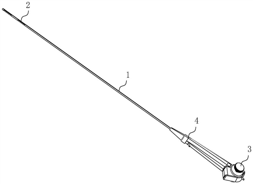
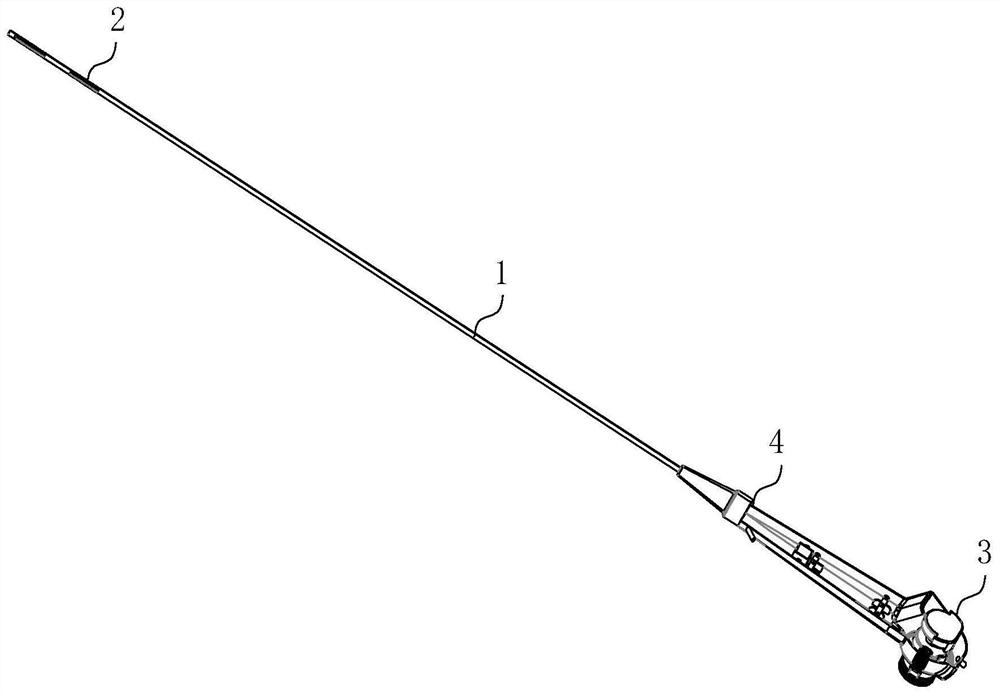
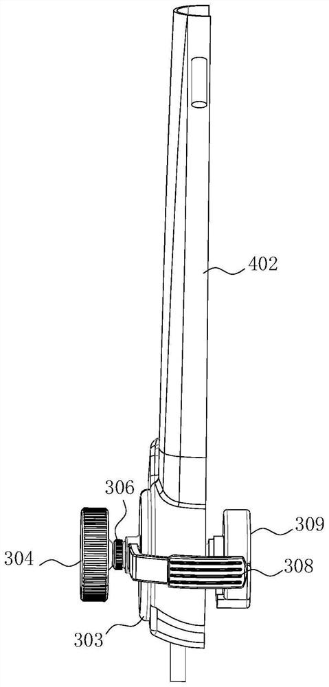
[0044] See attached figure 1 - attached Figure 9 , the minimally invasive cardiac surgery assisting device of the present invention comprises:

[0045] A multi-chamber power hose 1, the multi-chamber power hose 1 at least includes three channels arranged along the length direction and passing through both ends, wherein one channel is used as a video acquisition channel, one channel is used as a liquid channel, and one channel is used as a gas channel;

[0046] A fiberscope or electronic mirror built into the video acquisition channel;

[0047] A precision head end 2 arranged at one end of the multi-chamber power hose 1;

[0048] And the power handle 3 arranged at the other end of the multi-chamber power hose 1, the power handle 3 at least includes a first steel wire rope 301 and a second steel wire rope 302, and one end of the first steel wire rope 301 and the second steel wire rope 302 is connected to the power The handle 3 is connected, and the other end is connected to...

Embodiment 2

[0072] The difference between this embodiment and Embodiment 1 is:

[0073] The structure of the multi-chamber power hose 1 is a solid hose, and inside the hose, a plurality of passages are arranged along the axial direction from one end to the other end.

[0074] The precision head end 2 is a steel cap arranged at the end of the multi-chamber power hose 1, and the other ends of the first steel wire rope 301 and the second steel wire rope 302 are fixedly connected to the steel cap, and are symmetrical at 180 degrees set up.


PUM


Abstract

The invention discloses a minimally invasive cardiac surgery auxiliary device, belongs to the technical field of medical instruments, and aims at solving the problems that in the prior art, an intracardiac structure is difficult to explore in the surgery process, a surgery field cannot be exposed, and the surgery safety coefficient is low. The device comprises a multi-cavity power hose, wherein the multi-cavity power hose at least comprises three channels which are arranged in the length direction and penetrate through the two ends, and the three channels are divided into a video acquisition channel, a liquid channel and a gas channel; a fiber mirror or an electronic mirror which is arranged in the video acquisition channel; a precise head end which is arranged at one end of the multi-cavity power hose; a power handle which at least comprises a first steel wire rope and a second steel wire rope, wherein one end of the first steel wire rope and one end of the second steel wire rope areconnected with the power handle, the other end of the first steel wire rope and the other end of the second steel wire rope are connected with the precise head end, and the ends connected with the precise head end are located on the same section tangent plane passing through the axis, wherein the direction of the precise head end is adjusted through the power handle.

Description

technical field [0001] The invention belongs to the technical field of medical devices, and in particular relates to a minimally invasive heart surgery assisting device. Background technique [0002] The application of thoracoscopic surgery in cardiac surgery in foreign countries began in the early 1990s, and it has been more than 20 years, especially the application of robot-assisted systems, enabling it to complete a variety of cardiac surgery. Thoracoscopic cardiac surgery started late in China, and thoracoscopy was applied to cardiac surgery in early 2000, and most of them did not use robot-assisted systems. The application of thoracoscopy in cardiac surgery is considered a technological revolution in the field of cardiac surgery and the beginning of the era of minimally invasive cardiac surgery. At present, the thoracoscopes used for cardiac surgery at home and abroad are all rigid and large-caliber, and there is no report on the use of ultra-fine fiberscopes to assist...

Claims


Application Information

Patent Timeline
Patent Type & Authority Applications(China)
IPC IPC(8): A61B17/00A61B90/00A61B90/30
CPCA61B17/00234A61B2017/00243A61B2017/0034A61B2217/005A61B2217/007A61B90/08A61B90/30A61B90/361A61B90/37A61B2090/306A61B2090/3614
Inventor 林柏松王巍刘欣梅熊志勇朱林涛郭旭东陈月张兴芳张强张甲鹏赵丹
Owner 长春艾迪尔医用科技发展有限公司
Learn More