
Life health monitoring management and control equipment

A technology of health monitoring and equipment, applied in diagnostic recording/measurement, medical science, sensors, etc., can solve the problems of no bedside adjustment, bed heating, no guardrail shrinkage, etc., and achieve simple structure, easy heating, and convenient use Effect

Inactive Publication Date: 2021-03-12
王纪华
View PDF0 Cites 2 Cited by
  • Summary
  • Abstract
  • Description
  • Claims
  • Application Information

AI Technical Summary

Problems solved by technology

[0004] The purpose of the present invention is to solve the shortcomings of the existing life and health monitoring and control equipment, which do not have the function of shrinking the guardrail, the function of adjusting the head of the bed and the function of heating the bed body, and propose a Life and health monitoring and control equipment

Method used


Image

  • Life health monitoring management and control equipment
  • Life health monitoring management and control equipment
  • Life health monitoring management and control equipment

Examples


Embodiment 1

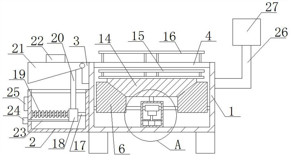
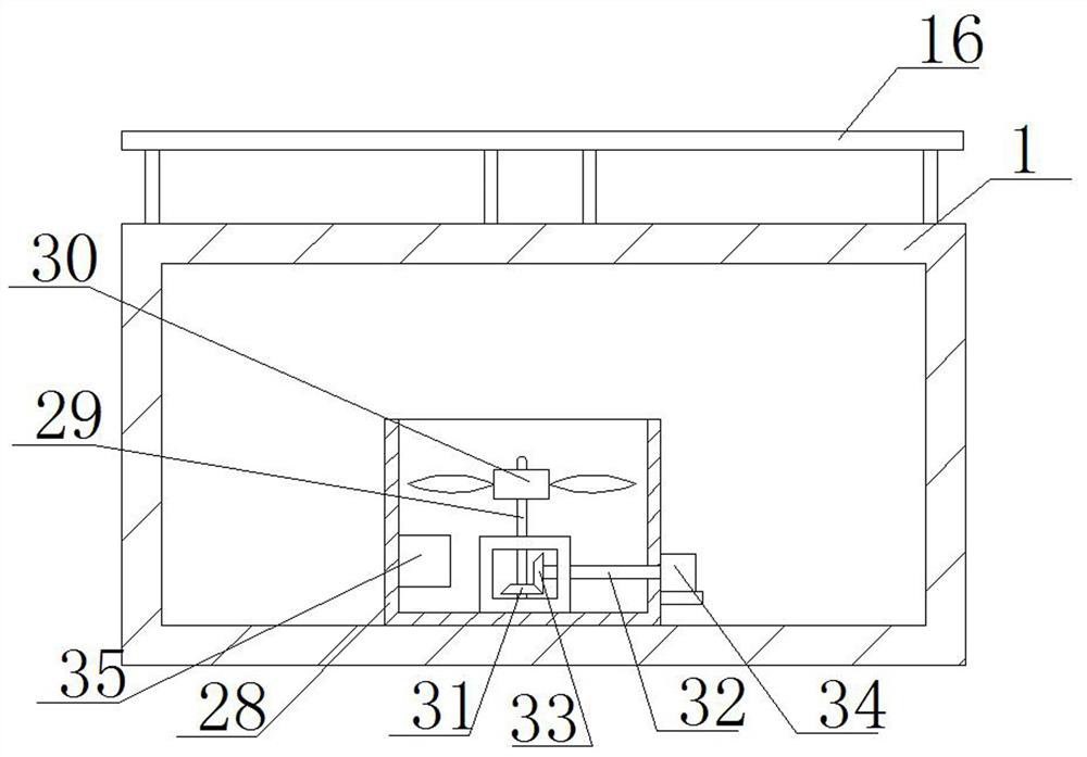
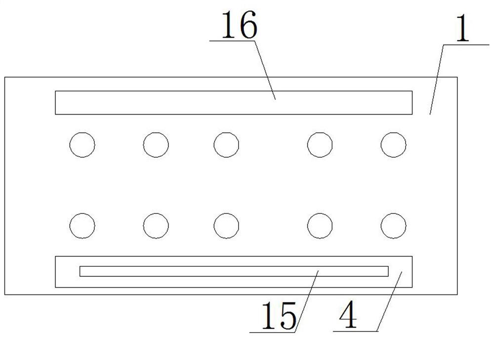
[0030] refer to Figure 1-6 , a life and health monitoring and control equipment, including a bed body 1, a side frame 2 is fixedly installed on one side of the bed body 1, a hinged seat 3 is fixedly installed on one side of the bed body 1, and a first length is provided on the top of the bed body 1. Hole 4, screw rod 5 is connected with rotation in bed body 1, two inclined blocks 6 are threaded on screw rod 5, worm rod 8 is fixedly connected on screw rod 5, and adjustment frame 7 is fixedly installed on the bottom inner wall of bed body 1, adjusts A partition 9 is fixedly installed in the frame 7, and the partition 9 is rotatably connected with a first rotating rod 10, and one end of the first rotating rod 10 is fixedly connected with a turbine 11, and the turbine 11 is engaged with the worm rod 8, and the bottom of the partition 9 A first motor 12 is fixedly installed, and the output shaft of the first motor 12 is fixedly connected with the first rotating rod 10 .

[0031] ...

Embodiment 2

[0041] refer to Figure 1-6 , a life and health monitoring and control equipment, including a bed body 1, a side frame 2 is welded and installed on one side of the bed body 1, a hinged seat 3 is welded and installed on one side of the bed body 1, and a first length is provided on the top of the bed body 1. Hole 4, screw rod 5 is connected with rotation in bed body 1, two inclined blocks 6 are threaded on screw rod 5, worm rod 8 is welded on screw rod 5, and adjustment frame 7 is welded and installed on the bottom inner wall of bed body 1, adjust A clapboard 9 is welded and installed in the frame 7, and a first rotating rod 10 is rotatably connected to the clapboard 9, and one end of the first rotating rod 10 is welded and connected with a turbine 11, and the turbine 11 is engaged with the worm rod 8, and the bottom of the clapboard 9 A first motor 12 is installed by welding, and the output shaft of the first motor 12 is welded to the first rotating rod 10 .

[0042]In this em...


PUM


Abstract

The invention belongs to the technical field of monitoring management and control equipment, particularly relates to life health monitoring management and control equipment, and aims to solve the problems that existing life health monitoring management and control equipment does not have a function of retracting a protective guard, a function of adjusting a bed head and a function of heating a bedbody. A side frame is fixedly installed on one side of the bed body, a hinge seat is fixedly installed on one side of the bed body, a first long hole is formed in the top of the bed body, a screw rodis rotatably connected into the bed body, two inclined blocks are in threaded connection with the screw rod, a worm is fixedly connected to the screw rod, and an adjusting frame is fixedly installedon the inner wall of the bottom of the bed body. According to the nursing bed convenient to use, the structure is simple, the protective guard can be contracted conveniently, the bed body can be heated conveniently, and the nursing bed is convenient for people to use.

Description

technical field [0001] The invention relates to the technical field of monitoring and control equipment, in particular to a life and health monitoring and control equipment. Background technique [0002] At present, the quality of sleep will have a very significant impact on human health. Insomniacs are likely to cause endocrine disorders, mental disorders, endanger physical health, affect memory, lead to depression, and even affect the nervous system and lead to cardiovascular diseases. According to statistics, nearly 35% of the population in my country has insomnia, and about 17% are in a relatively serious state. It can be seen that insomnia has become a common disease and has seriously affected people's normal life and work. Therefore Health monitoring and control devices have emerged to monitor people while they sleep. [0003] The existing life and health monitoring and control equipment does not have the function of shrinking the guardrail, and does not have the functi...

Claims


Application Information

Patent Timeline
IPC IPC(8): A61B5/00
CPCA61B5/00
Inventor 王纪华
Owner 王纪华
Learn More