Pipe fitting wiring supporting device
A technology for supporting devices and pipe fittings, which is applied in the direction of pipe supports, pipes/pipe joints/fittings, cable laying equipment, etc., which can solve problems such as unfavorable pipe fittings concealed work, pipe fitting deviation, workers' arms soreness, etc., to save storage space , easy to move, accurate positioning effect
- Summary
- Abstract
- Description
- Claims
- Application Information
AI Technical Summary
Problems solved by technology
Method used
Image
Examples
specific Embodiment approach 1
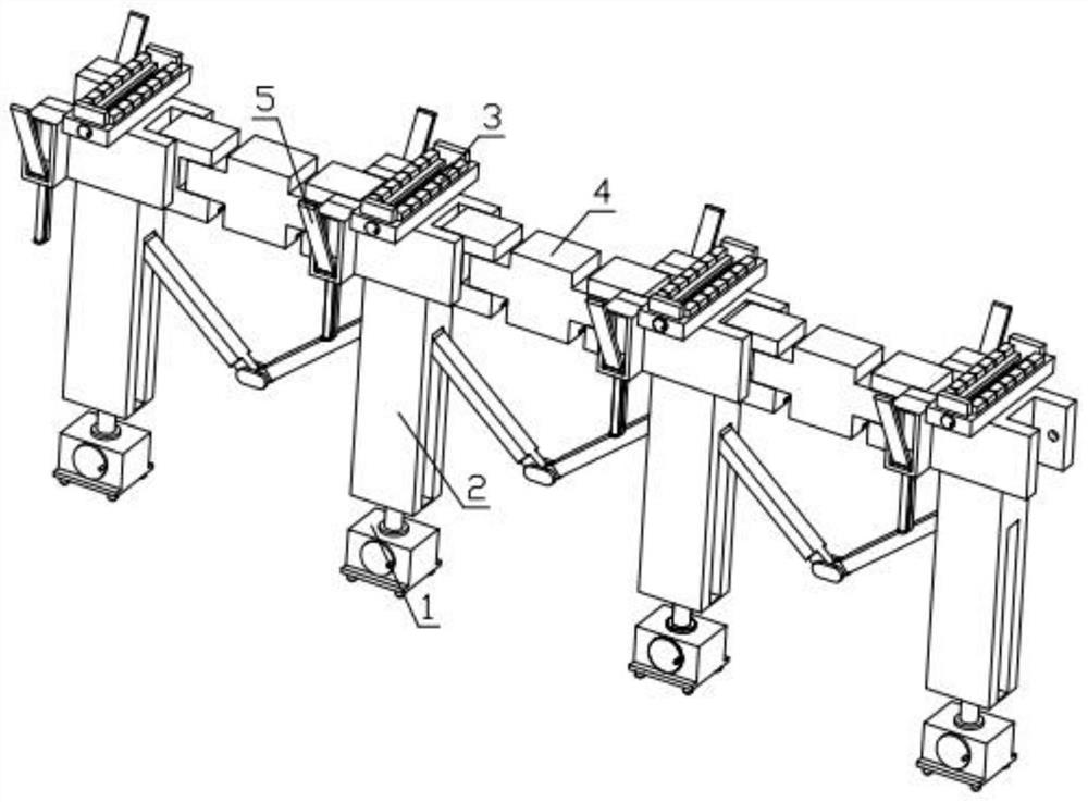
[0033] Combine below Figure 1-12 Describe this embodiment, a pipe fitting routing support device, including a bottom lifting mechanism 1, a connection and disassembly mechanism 2, a pipe fitting limit mechanism 3, an angle adjustment mechanism 4 and a wall locking mechanism 5, characterized in that: the bottom lifting mechanism Mechanism 1 is threadedly connected with connecting and dismounting mechanism 2, multiple connecting and dismounting mechanisms 2 are hingedly connected to each other, connecting and dismounting mechanism 2 is slidably installed in the groove provided on the angle adjustment mechanism 4, and the angle adjustment mechanism 4 is fixedly installed with a pipe limit mechanism 3. The two sides of the angle adjustment mechanism 4 are fixedly installed with a wall locking mechanism 5 .
specific Embodiment approach 2
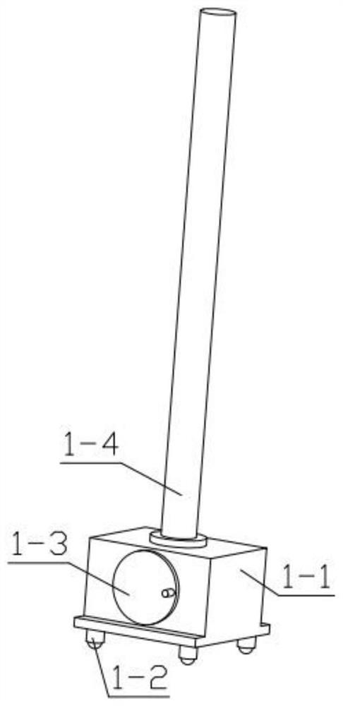
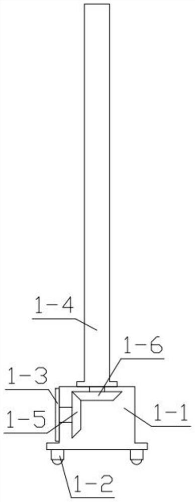
[0035] Combine below Figure 1-12 Describe this embodiment, this embodiment will further explain the first embodiment, the bottom lifting mechanism 1 includes a counterweight box 1-1, a universal wheel 1-2, a manual turntable 1-3, and a lifting threaded rod 1-4 , helical gear one 1-5, helical gear two 1-6, the bottom of the counterweight box 1-1 is fixedly equipped with universal wheels 1-2, and the groove of the counterweight box 1-1 is rotatably equipped with helical gears One 1-5, one side of the helical gear 1-5 passes through the counterweight box 1-1 and is fixedly installed with a manual turntable 1-3, and the second helical gear 1-6 is rotatably installed on the counterweight box 1-1 In the groove, helical gear one 1-5 is meshed with helical gear two 1-6, and helical gear two 1-6 is fixedly installed with lifting threaded rod 1-4.
specific Embodiment approach 3
[0037] Combine below Figure 1-12 Describe this embodiment, this embodiment will further explain the second embodiment, the connection and detachment mechanism 2 includes a lifting block 2-1, a side rod 2-2, a side rod 2 2-3, and a hinge 2-4, The lifting block 2-1 is threadedly connected with the lifting threaded rod 1-4, a side bar 2-2 is hinged in the groove on one side of the lifting block 2-1, and the other end of the side bar 2-2 is hinged with a hinge 2- 4. The second side bar 2-3 is hinged in the groove on the other side of the lifting block 2-1, and the hinge 2-4 is hinged with the second side bar 2-3.
PUM
 Abstract
Description
Claims
Application Information
 - R&D
- Intellectual Property
- Life Sciences
- Materials
- Tech Scout
- Unparalleled Data Quality
- Higher Quality Content
- 60% Fewer Hallucinations
Browse by: Latest US Patents, China's latest patents, Technical Efficacy Thesaurus, Application Domain, Technology Topic, Popular Technical Reports.
© 2025 PatSnap. All rights reserved.Legal|Privacy policy|Modern Slavery Act Transparency Statement|Sitemap|About US| Contact US: help@patsnap.com


