Fish ball forming device for food processing
A forming device and food processing technology, applied in food forming, application, food science, etc., can solve the problems of slow speed, different fish balls, different sizes of fish balls, etc., to achieve consistent size and shape, and fast speed Effect
- Summary
- Abstract
- Description
- Claims
- Application Information
AI Technical Summary
Problems solved by technology
Method used
Image
Examples
Embodiment 1
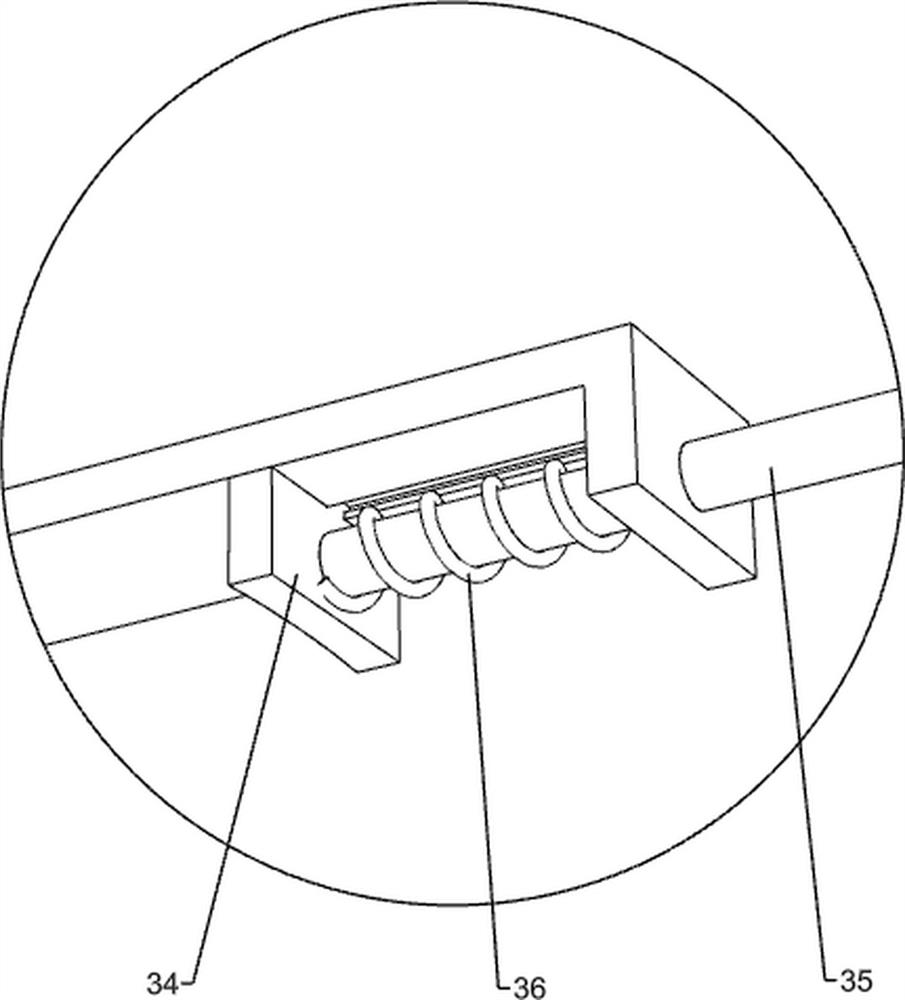
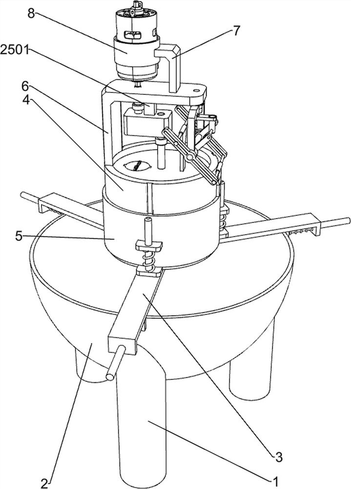
[0025] Such as figure 1 As shown, it includes a pot leg 1, a pot body 2, a support frame 3, a pill extruder 4, a ring knife 5, a large L-shaped mounting frame 6, a small L-shaped mounting frame 7, a fixed ring 8, a motor 9, and a first rotating shaft 10. The first belt pulley 11, the second rotating shaft 12, the second belt pulley 13 and the swing device, the pot body 2 is fixedly installed on the pot leg 1, and three support frames 3 are evenly arranged on the pot body 2, and the support frame 3 is provided with Pill squeezer 4, the bottom of pill squeezer 4 is provided with a plurality of circular holes, and the outer side of pill squeezer 4 slides up and down to connect with ring knife 5. Both pill squeezer 4 and ring knife 5 are made of stainless steel. The upper part of pill squeezer 4 is left The side is fixedly installed with a large L-shaped mounting frame 6, and the right side of the large L-shaped mounting frame 6 is fixedly installed with a small L-shaped mounting ...
Embodiment 2
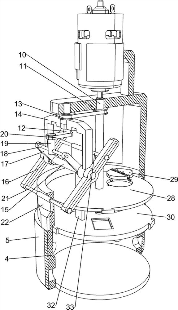
[0028] Specifically referring to 3, the swing device also includes a U-shaped connecting frame 14, a first connecting column 15, a first swinging rod 16, a second swinging rod 17, a second connecting rod 18, a first sliding rod 19, and a connecting rod 20. , the third connecting column 21 and the first connecting piece 22, the second rotating shaft 12 is rotatably connected with a U-shaped connecting frame 14, and the bottom of the U-shaped connecting frame 14 is rotatably connected with the first connecting column 15 between the front and rear side walls, the first The first swing rod 16 is installed at the front and rear ends of the connecting column 15, and the two first swing rods 16 are installed on the outside of the U-shaped connecting frame 14, and the second swing rod 17 is installed at the front and rear ends of the first connecting column 15. 17 is installed on the inner side of the U-shaped connecting frame 14, a second connecting column 18 is fixedly connected betw...
Embodiment 3
[0031] specific reference Figure 2 to Figure 6 As shown, it also includes a shaft coupling 23, an input shaft 24, a speed reducer 25, a connecting block 2501, an output shaft 26, a threaded rod 27 and a first circular pressure plate 28, and the bottom surface of the upper part of the large L-shaped mounting frame 6 is fixedly installed with a connection Block 2501, the bottom surface of the connecting block 2501 is fixedly connected with a speed reducer 25, the speed reducer is a prior art and will not be introduced here, the input shaft 24 on the speed reducer 25 is connected with the first rotating shaft 10 through a coupling 23, The output shaft 26 is fixedly connected with the upper end of a threaded rod 27 through a coupling 23, and the threaded rod 27 is threaded with a first circular pressing plate 28, which is slidably connected up and down in the pill squeezer 4.
[0032] Turn on the motor 9, when the first circular pressing plate 28 presses the stuffing down, the ou...
PUM
 Abstract
Description
Claims
Application Information
 - R&D
- Intellectual Property
- Life Sciences
- Materials
- Tech Scout
- Unparalleled Data Quality
- Higher Quality Content
- 60% Fewer Hallucinations
Browse by: Latest US Patents, China's latest patents, Technical Efficacy Thesaurus, Application Domain, Technology Topic, Popular Technical Reports.
© 2025 PatSnap. All rights reserved.Legal|Privacy policy|Modern Slavery Act Transparency Statement|Sitemap|About US| Contact US: help@patsnap.com


