Waterproof test device for rain shoes
A technology of testing device and rain boots, which is applied in the direction of using liquid/vacuum for liquid tightness measurement, etc., can solve the problems of inconvenient waterproof detection, unintuitive inspection results, etc., and achieve the effect of intuitionistic test results.
- Summary
- Abstract
- Description
- Claims
- Application Information
AI Technical Summary
Problems solved by technology
Method used
Image
Examples
Embodiment 1
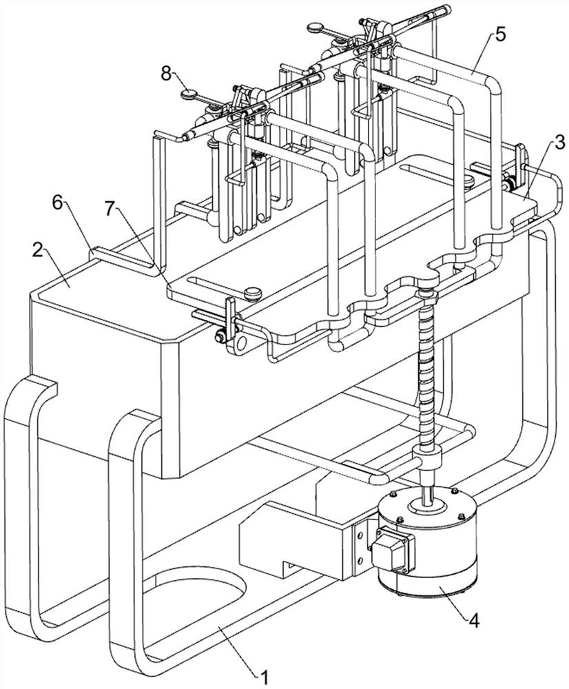
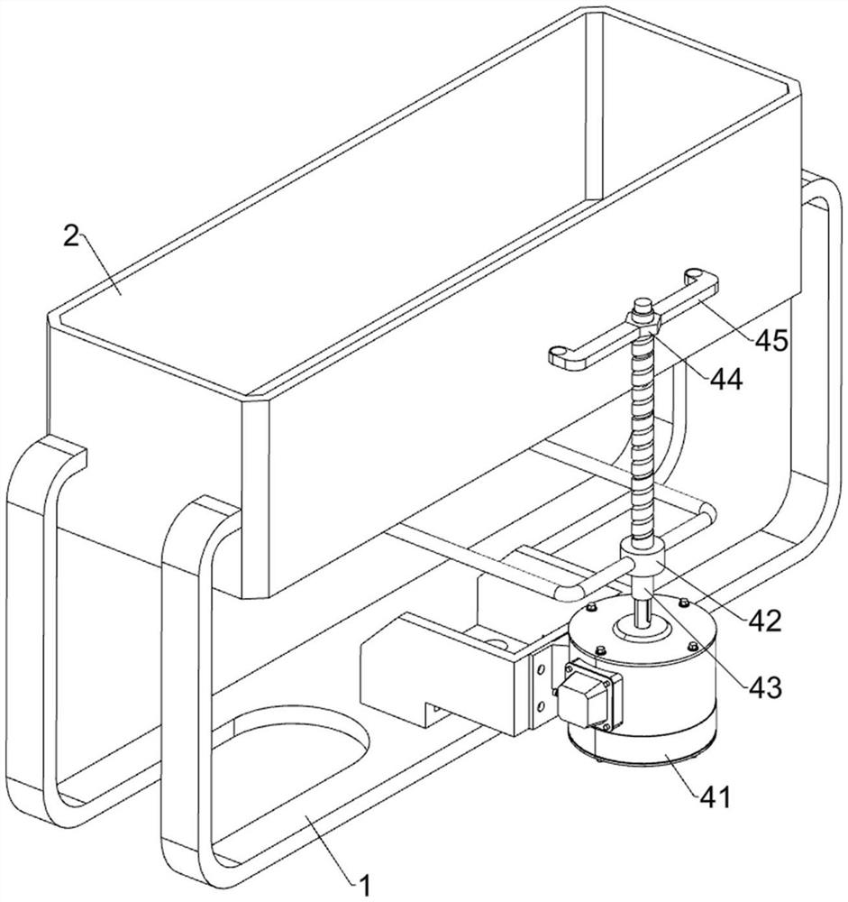
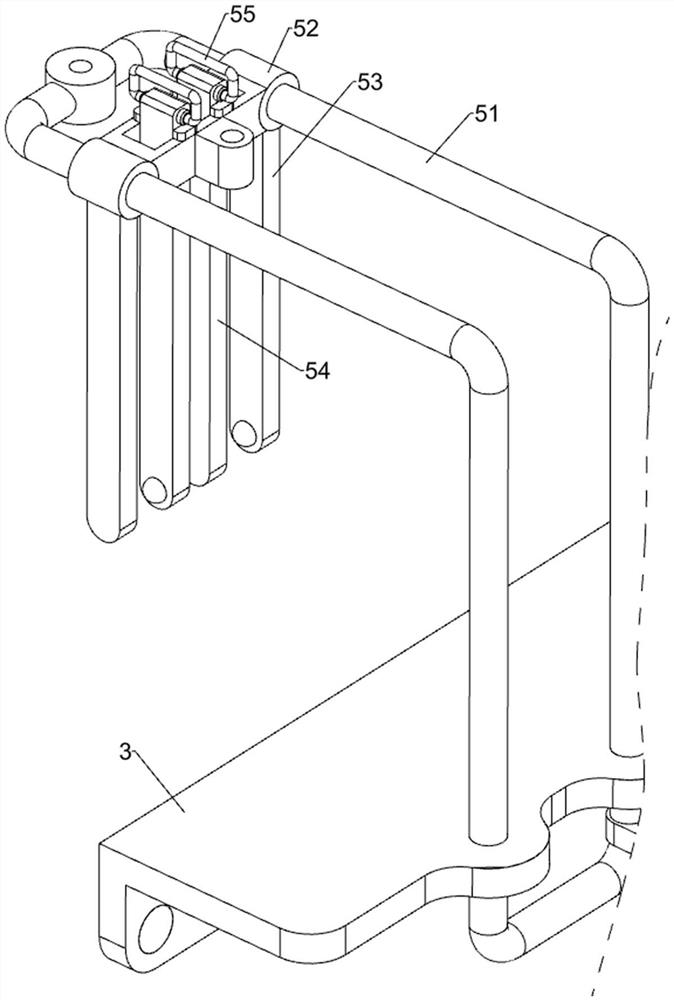
[0023] A waterproof test device for rain boots, such as Figure 1-4 As shown, it includes a frame 1, a liquid storage frame 2, a mounting plate 3, a driving assembly 4, a clamping assembly 5 and a pushing assembly 6. The upper part of the frame 1 is fixed with the liquid storage frame 2 through bolts, and the front The upper part of the side is fixed with a mounting plate 3 by bolts, the front side of the frame 1 is provided with a driving assembly 4, and the mounting plate 3 is provided with a clamping assembly 5, which is matched with the driving assembly 4, and the liquid storage frame 2 is connected with the clamping assembly. A pushing component 6 is arranged between the components 5 .
[0024] When it is necessary to carry out a waterproof test on the rain boots, first add a sufficient amount of water to the liquid storage frame 2, then place the rain boots between the clamping components 5, and then control the driving component 4 to start working, and the driving compo...
Embodiment 2
[0032] On the basis of Example 1, such as figure 1 and Figure 5 As shown, a support assembly 7 is also included. The support assembly 7 includes a support plate 71, a first rack 72, a rotating rod 73, a gear 74, a connecting rod 75, and a second rack 76. The rear side of the mounting plate 3 is slidingly designed. There is a support plate 71, the left and right sides of the support plate 71 are connected with the first rack 72, the left and right sides of the mounting plate 3 are rotatably connected with a rotating rod 73, and the left and right sides of the rotating rod 73 are connected with two gears 74 by keys. The inner gear 74 meshes with the first rack 72 , and the outside of the lower part of the right angle frame 51 is connected with a connecting rod 75 , and the outside of the connecting rod 75 is connected with a second rack 76 , and the second rack 76 meshes with the gear 74 on the outside.
[0033] When the rain boots need to be placed between the first splint 53 a...
Embodiment 3
[0035] On the basis of Example 2, such as figure 1 and Figure 6 As shown, a warning assembly 8 is also included. The warning assembly 8 includes a slide bar 81, a hollow sphere 82 and a warning plate 83. The rear side of the right angle frame 51 is slidably provided with a slide bar 81, and the bottom of the slide bar 81 is connected with a hollow sphere 82. The right-angle frame 51 rear side rotation type is provided with a warning plate 83, and the warning plate 83 cooperates with the slide bar 81.
[0036] When placing the rain boots, the slide rod 81 and the hollow ball 82 are positioned inside the rain boots. If the waterproof performance of the rain boots is poor, water will enter the inside of the rain boots, causing the hollow ball 82 to float and drive the slide bar 81 to move upward. Moving will drive the warning plate 83 to rotate upwards, so that the user knows that the waterproof performance of the rain boots is poor. If the waterproof performance is better, the...
PUM
 Abstract
Description
Claims
Application Information
 - Generate Ideas
- Intellectual Property
- Life Sciences
- Materials
- Tech Scout
- Unparalleled Data Quality
- Higher Quality Content
- 60% Fewer Hallucinations
Browse by: Latest US Patents, China's latest patents, Technical Efficacy Thesaurus, Application Domain, Technology Topic, Popular Technical Reports.
© 2025 PatSnap. All rights reserved.Legal|Privacy policy|Modern Slavery Act Transparency Statement|Sitemap|About US| Contact US: help@patsnap.com


