
Automatic instrument base capable of accurately adjusting angle

A technology for adjusting angles and instruments, which is applied in the direction of instruments, measuring instrument components, measuring devices, etc., and can solve problems such as inability to adjust the orientation of instruments, inconvenient actual use, fixed and non-adjustable instruments, etc.

Inactive Publication Date: 2021-03-09
温州宇途机械科技有限公司
View PDF7 Cites 3 Cited by
  • Summary
  • Abstract
  • Description
  • Claims
  • Application Information

AI Technical Summary

Problems solved by technology

[0005] In order to solve the above technical problems, the present invention provides an automatic instrument base with precise angle adjustment, so as to solve the problem that the orientation of the instrument cannot be adjusted when the automatic instrument mounting seat in the above patent is in use, and the instrument is fixed and cannot be adjusted, which makes it inconvenient to operate according to the The position of the operator adjusts the angle of the instrument, which causes inconvenience to the actual use

Method used


Image

  • Automatic instrument base capable of accurately adjusting angle
  • Automatic instrument base capable of accurately adjusting angle
  • Automatic instrument base capable of accurately adjusting angle

Examples


Embodiment

[0034] as attached figure 1 To attach Figure 9 Shown:

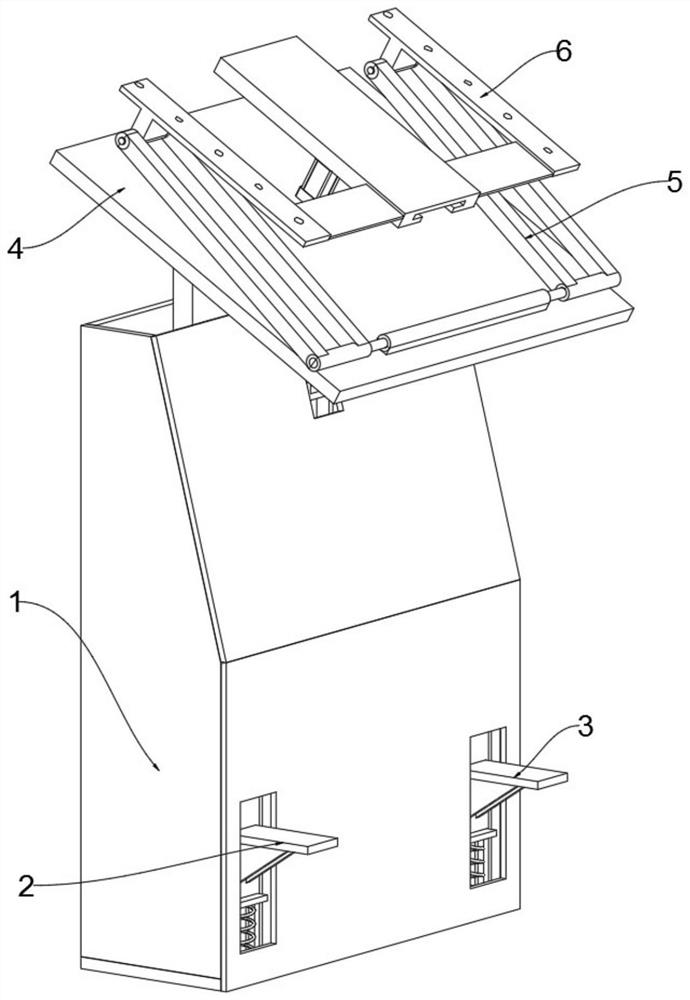
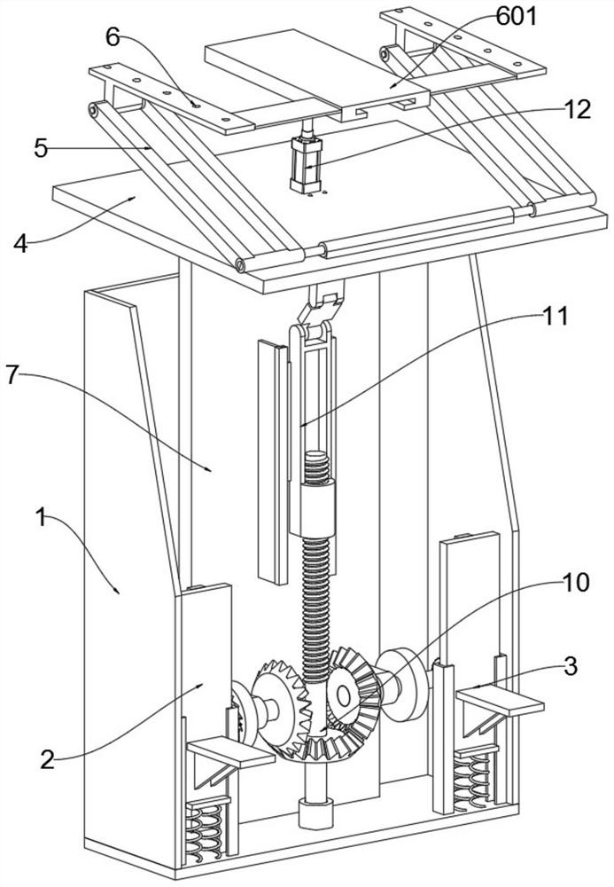
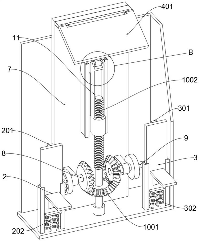
[0035]The invention provides an automatic instrument base for precise angle adjustment, including a housing 1, an up-adjustment foot 2, a down-adjustment foot 3, an adjustment plate 4, a lifting auxiliary frame 5, an instrument installation frame 6, an up-regulation transmission shaft 8, and a down-regulation transmission shaft 9 , adjusting shaft 10, lifting rod 11, cylinder 12; the inner bottom plate of the housing 1 is fixedly connected with the column 7; the upward adjustment foot 2 is slidably connected in the lifting seat 101 on the left side of the housing 1; the lower adjustment foot 3 is also slidably connected to the housing 1 Inside the lifting seat 101 on the right side; the bottom of the adjusting plate 4 is connected to the bottom plate 401 and the rear side is connected to the column 7 through hinges; the lower end of the front side of the lifting auxiliary frame 5 is connected to the upper surface of the...


PUM


Abstract

The invention provides an automatic instrument base capable of accurately adjusting an angle. The automatic instrument base comprises a shell, an up-adjusting pedal, a down-adjusting pedal, an adjusting plate, a lifting auxiliary frame, an instrument mounting frame, an up-adjusting transmission shaft and a down-adjusting transmission shaft, wherein a stand column is fixedly connected to a bottom plate on the inner side of the shell, the up-adjusting pedal is slidably connected to the interior of a lifting seat on the left side of the shell, the down-adjusting pedal is slidably connected to theinterior of a lifting seat on the right side of the shell, the lower part of the adjusting plate is connected with the rear side of the bottom plate and is connected to the stand column in a hinged mode, the lower end of the front side of the lifting auxiliary frame is connected to the upper surface of the adjusting plate in a hinged mode, a lower supporting shaft of the instrument mounting frameis rotationally connected to the upper end of the lifting auxiliary frame in a hinge mode, and the middle of a shaft body of the up-adjusting transmission shaft is rotationally connected to the frontsurface of the stand column through a bearing. It can be seen that the instrument installation base of the structure has the function of adjusting the direction of an instrument, adjustment can be carried out through the pedals below the instrument installation base, operation convenience is improved, and the probability of misoperation is reduced.

Description

technical field [0001] The invention belongs to the technical field of instrument bases, and more specifically relates to an automatic instrument base for precise angle adjustment. Background technique [0002] Automation equipment is often equipped with instruments that display various parameters, and the instruments are often embedded on the equipment through the instrument base. Automated instruments are power measurement and control equipment that provide solutions for power parameter measurement, power quality monitoring and analysis, and electrical equipment control. , In the actual production, it also plays a role in controlling the production process. The automation instrument is composed of a number of automation components and is an automation technology tool with relatively complete functions. It generally has several functions at the same time, such as measurement, display, recording or measurement, control, alarm, etc. The automation instrument itself is a syst...

Claims


Application Information

Patent Timeline
IPC IPC(8): F16M11/04F16M11/12F16M11/18G01D11/00
CPCF16M11/04F16M11/043F16M11/12F16M11/18G01D11/00
Inventor 全林寒
Owner 温州宇途机械科技有限公司
Learn More