
Fabricated building construction device

A building construction and prefabricated technology, applied in the construction, building structure, processing of building materials, etc., can solve the problems of the extruded board not reaching 90 degrees, the collapse of the wall board, the equipment damage of the supporting device, etc. Practicality and applicability, the effect of reducing the impact force and improving the service life

Inactive Publication Date: 2021-03-09
胡恒文
View PDF1 Cites 3 Cited by
  • Summary
  • Abstract
  • Description
  • Claims
  • Application Information

AI Technical Summary

Problems solved by technology

[0003] The Chinese utility model with the patent number CN201920663781.0 in the prior art discloses a prefabricated building construction support device, including a bottom plate, a rotating device is clamped on the upper surface of the bottom plate, and the top end of the rotating device is fixedly connected with a screw thread A column, the surface of the threaded column is threadedly connected with a threaded cylinder, the left and right sides of the threaded cylinder are fixedly connected with a first movable device, and the lower surface of the first movable device is fixedly connected with a slider, the prefabricated building The construction support device adjusts the support height of the device by rotating the threaded column, and makes the device suitable for walls with different angles by controlling the first electric push rod and the second electric push rod, but the device is not suitable for walls perpendicular to the ground. Assembling the wall panel support, the rotation angle of the extruded plate cannot reach 90 degrees, so that when the extruded plate supports the assembled wall panel perpendicular to the ground, there is a gap between the extruded plate and the assembled wall panel, which cannot completely resist If it is closed, the wall panel will collapse, resulting in damage to the equipment of the supporting device.

Method used


Image

  • Fabricated building construction device
  • Fabricated building construction device
  • Fabricated building construction device

Examples


Embodiment 1

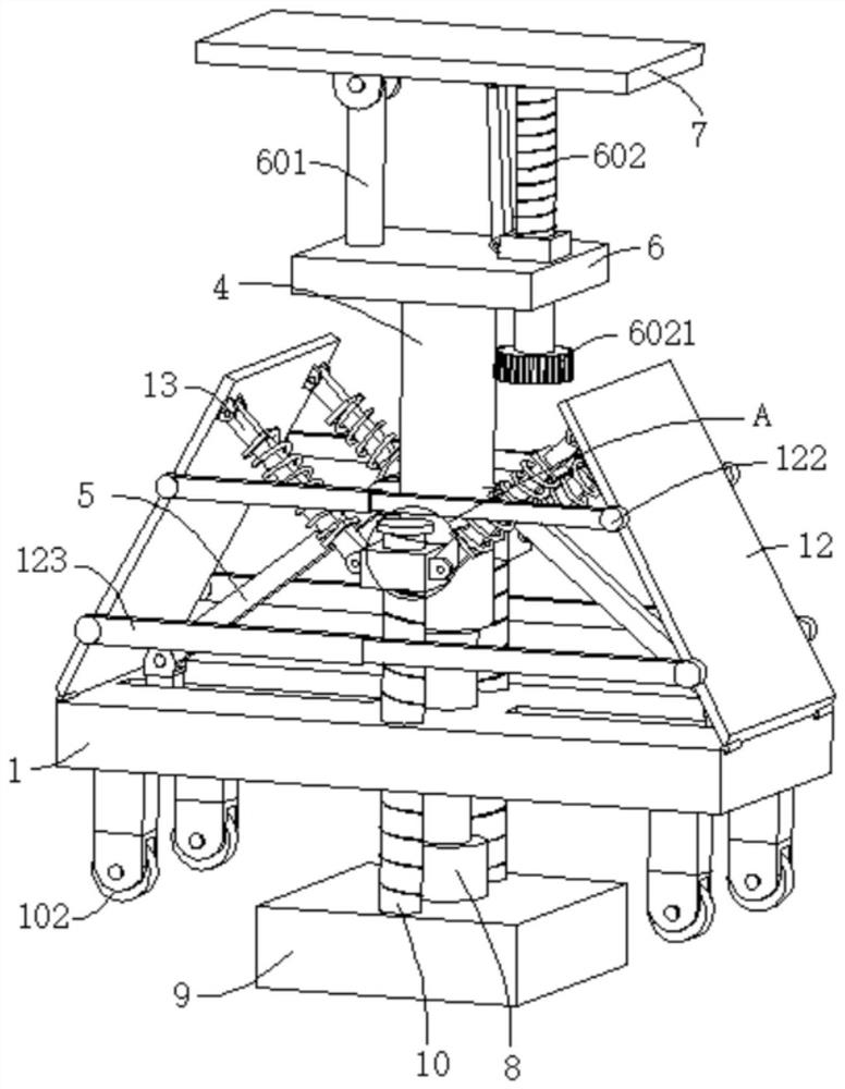
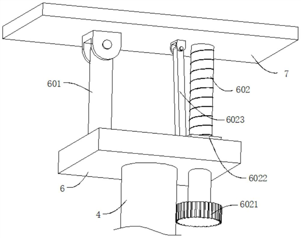
[0033] refer to Figure 1-6 , a prefabricated building construction device, comprising a working board 1, the bottom wall of the working board 1 is connected with a roller 102, a cavity is dug in the working board 1, a motor 2 is connected to the inner wall of the cavity, and the output end of the motor 2 passes through the working The plate 1 is also connected with a rotating shaft 201, the end of the rotating shaft 201 away from the motor 2 is connected with a first screw 3, the outer wall of the first screw 3 is threadedly connected with a threaded pipe 4, and the outer walls of both sides of the working plate 1 are dug with chute 101, the chute The inner wall of 101 is slidably connected with a slider 1011, the slider 1011 and the outer wall of the threaded pipe 4 are respectively connected with a first U-shaped plate 1012 and a second U-shaped plate 401, and the first U-shaped plate 1012 and the second U-shaped plate 401 are connected Connecting plate 5 is arranged, and t...

Embodiment 2

[0038] refer to figure 1 , a prefabricated building construction device, which is basically the same as Embodiment 1, furthermore, the bottom of the working board 1 is connected to a cylinder 8, and the end of the cylinder 8 away from the working board 1 is fixedly connected to a base 9.

[0039] Since the device is supporting the assembly of the wallboard, the rollers 102 at the bottom may move, resulting in a poor support effect of the device. By setting the cylinder 8, the cylinder 8 is controlled to work, so that the output power rod of the cylinder 8 pushes the working plate 1 and The distance between the bases 9 becomes large, so that the bases 9 contact the ground, and the rollers 102 move up with the working plate 1 and leave the ground, so as to prevent the device from shaking arbitrarily when supporting work, and improve the stability of the device.

Embodiment 3

[0041] refer to figure 1 , figure 2 , Figure 5 , Image 6 and Figure 7 , a prefabricated building construction device, which is basically the same as Embodiments 1 and 2, furthermore, the outer walls on both sides of the base 9 are connected with baffles 12 through hinges, and a supporting mechanism is connected between the baffles 12 and the base 9 .

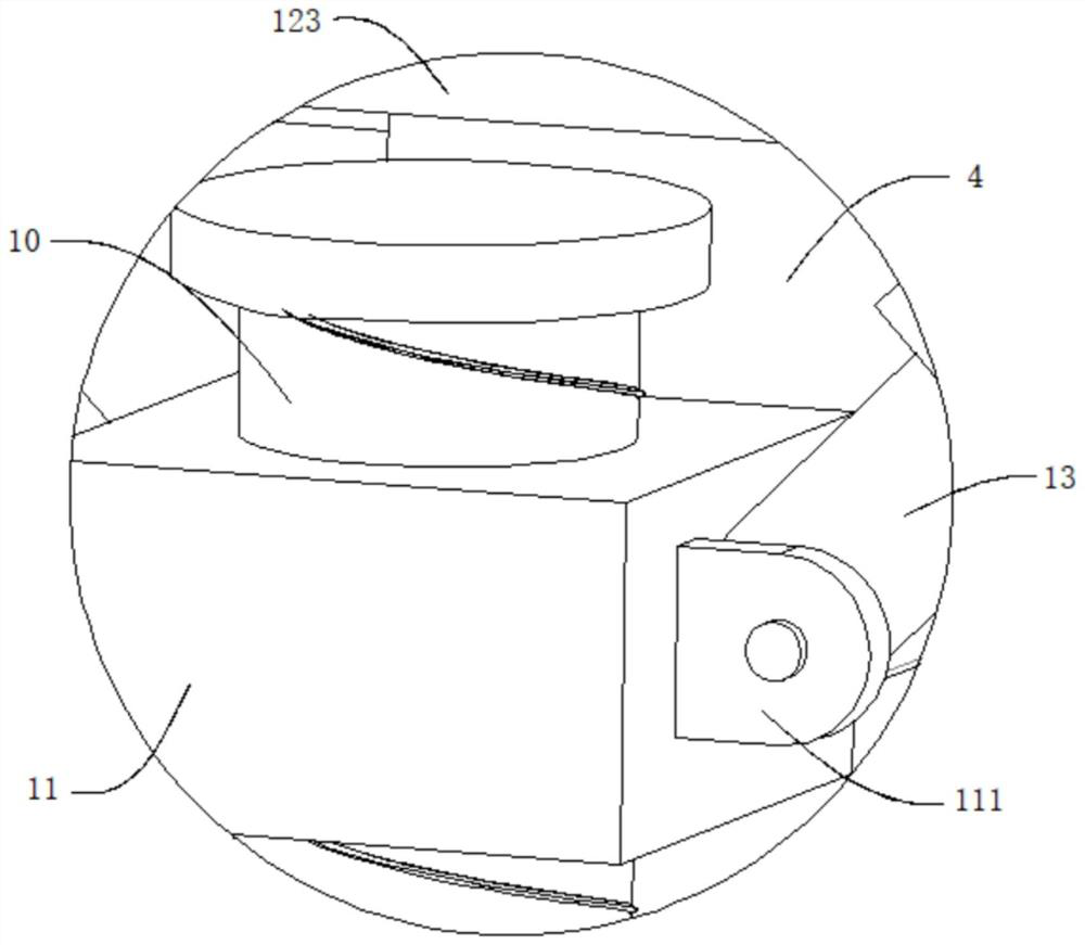
[0042] The support mechanism includes a third screw rod 10, which is rotatably connected in the base 9 through bearings, and the third screw rod 10 is threadedly connected with the working plate 1, and the outer wall of the third screw rod 10 is threadedly connected with a second sleeve 11, and the second sleeve A support plate 13 is connected between the cylinder 11 and the baffle plate 12 .

[0043] Both ends of the support plate 13 are respectively movably connected with a third U-shaped plate 111 and a fourth U-shaped plate 121, the third U-shaped plate 111 is fixedly connected to the outer wall of the second sleeve...


PUM


Abstract

The invention discloses a fabricated building construction device, and belongs to the technical field of building construction. The fabricated building construction device comprises a working plate, idler wheels are connected to the bottom wall of the working plate, a cavity is dug in the working plate, a motor is connected to the inner wall of the cavity, the output end of the motor penetrates through the working plate and is connected with a rotating shaft, the end, away from the motor, of the rotating shaft is connected with a first screw rod, a threaded pipe is in threaded connection withthe first screw rod, sliding grooves are formed in the outer walls of the two sides of the working plate, sliding blocks are slidably connected to the inner walls of the sliding grooves, first U-shaped plates and second U-shaped plates are connected to the sliding blocks and the outer walls of the threaded pipes correspondingly, connecting plates are connected between the first U-shaped plates andthe second U-shaped plates, fixing plates are fixedly connected to the tops of the threaded pipes, and straight rods are connected to the top outer walls of the fixing plates. The rotating angle of an extrusion plate can be greatly adjusted, so that the extrusion plate is suitable for supporting a fabricated wallboard perpendicular to the ground and other wallboard placement angles, and the practicability and applicability of the device are greatly improved.

Description

technical field [0001] The invention relates to the technical field of building construction, in particular to a prefabricated building construction device. Background technique [0002] Building construction refers to the production activities in the implementation stage of engineering construction. It is the construction process of various buildings. It can also be said to be the process of turning various lines on the design drawings into real objects at designated locations. During construction, it is necessary to To support the assembled wall panels and wait for the adhesion of the waterproof adhesive surface, most of the prefabricated building construction support devices currently used still have the problem of not being able to automatically adjust the support angle, which greatly reduces the practicability of the support device. [0003] The Chinese utility model with the patent number CN201920663781.0 in the prior art discloses a prefabricated building construction...

Claims


Application Information

Patent Timeline
IPC IPC(8): E04G25/04E04G25/06E04G21/16E04G21/26
CPCE04G25/04E04G25/06E04G21/16E04G21/26
Inventor 胡恒文
Owner 胡恒文
Learn More