Rapid replacement device for RG-RH vacuum degassing furnace tank car drag chain

A vacuum degassing furnace, RG-RH technology, applied in the direction of lifting device, lifting frame, etc., can solve the problems of difficult replacement, heavy pipeline weight, difficult replacement operations, etc., to achieve good promotion value, save manpower, and improve efficiency. Effect

Pending Publication Date: 2021-03-09
SD STEEL RIZHAO CO LTD
View PDF5 Cites 0 Cited by
  • Summary
  • Abstract
  • Description
  • Claims
  • Application Information

AI Technical Summary

Problems solved by technology

[0002] In the replacement and maintenance work of the drag chain of the RH vacuum degassing furnace, we often encounter that the drag chain is damaged by individual joints, causing the entire drag chain to twist, break, deform, tilt or even fall to the ground, which will seriously cause pipelines and Line damage, scratches, breakage, etc., seriously affect the normal production and operation of the degassing furnace, and must be replaced and repaired
However, due to the long tow chain of these equipment, there are many tow cable lines, various hydraulic and gas pipelines inside the tow chain, and the weight of the pipeline is large, and it is easy to get entangled when scattered, so it is difficult to replace
One is that after the tow chain is dismantled, the cable lines, hydraulic and gas pipelines towed by it will fall freely and scatter, and it is not easy to collect according to the original position; Some work areas are relatively narrow, and it is not easy to change operations due to the large number of people. Third, manual handling and moving pipelines are prone to misalignment and winding. Can cause downtime and affect production

Method used


Image

  • Rapid replacement device for RG-RH vacuum degassing furnace tank car drag chain

Examples


Embodiment Construction

[0011] The present invention is described in further detail now in conjunction with accompanying drawing.

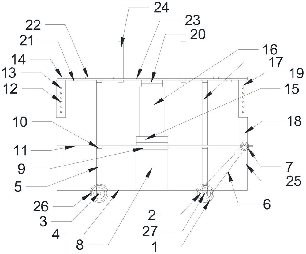
[0012] Such as figure 1 As shown, a RG-RH vacuum degassing furnace tank car drag chain quick replacement device, including a base plate 4, is characterized in that: the upper end of the base plate 4 is provided with support plates 25 on both sides, and the upper ends of the two support plates 25 are provided with two layers. There are lifting devices around the upper end of the board 11 and the second floor board 11. The upper end of the lifting device is provided with a jacking frame beam 23. The upper end of the jacking frame beam 23 is provided with frame side beams 14 on both sides, and the upper middle of the bottom plate 4 is provided with a support beam. 8. The upper end of the support beam 8 is provided with a bottom beam 9, and the bottom beam 9 passes through the second-layer board 11 and the upper end is provided with a base 15, the upper end of the base 15 is...


PUM


Abstract

The invention discloses a rapid replacement device for RG-RH vacuum degassing furnace tank car drag chain. The rapid replacement device comprises a bottom plate, supporting plates are arranged on thetwo sides of the upper end of the bottom plate, a two-layer plate is arranged at the upper ends of the two supporting plates, lifting devices are arranged on the periphery of the upper end of the two-layer plate, jacking frame beams are arranged at the upper ends of the lifting devices, and frame side beams are arranged on the two sides of the upper ends of the jacking frame beams. A supporting beam is arranged in the middle of the upper side of the bottom plate, a bottom cross beam is arranged at the upper end of the supporting beam and penetrates through the upper end of the two-layer plateto be provided with a base, a jack is arranged at the upper end of the base, and a top cross beam is arranged at the upper end of the jack. Jacking frame lower cross beams are arranged on the lower sides of the jacking frame beams, a plurality of jacking frame beams are arranged on the upper sides of the jacking frame beams, and drag chain baffles are arranged at the two ends of the upper sides ofthe jacking frame beams. The jack is used for jacking the jacking frame beams, so that the weight of various pipelines in the drag chain is pressed on the jacking frame beams, and the drag chain canbe freely disassembled, overhauled and replaced.

Description

technical field [0001] The invention relates to a quick replacement device for drag chains of RG-RH vacuum degassing furnace tankers. Background technique [0002] In the replacement and maintenance work of the drag chain of the RH vacuum degassing furnace, we often encounter that the drag chain is damaged by individual joints, causing the entire drag chain to twist, break, deform, tilt or even fall to the ground, which will seriously cause pipelines and Line damage, scratches, breakage, etc., seriously affect the normal production and operation of the degassing furnace, and must be replaced and repaired. However, due to the long drag chains of these devices, there are many tow cable lines, various hydraulic and gas pipelines inside the drag chains, and the weight of the pipelines is large, and they are easily entangled when they are scattered, so it is difficult to replace them. One is that after the tow chain is dismantled, the cable lines, hydraulic and gas pipelines tow...

Claims


Application Information

Patent Timeline
Patent Type & Authority Applications(China)
IPC IPC(8): B66F7/10B66F7/28
CPCB66F7/10B66F7/28
Inventor 张明王思清张广鑫马德福
Owner SD STEEL RIZHAO CO LTD
Why Eureka
Try Eureka