
Battery replacing method, battery replacing station and battery replacing cabinet

An electric method and power station technology, applied in charging stations, electric vehicle charging technology, electric vehicles, etc., can solve the problems of high construction cost of charging and swapping stations, sparse outlets, and large investment in charging and swapping outlets

Inactive Publication Date: 2021-03-09
杨天宝
View PDF0 Cites 0 Cited by
  • Summary
  • Abstract
  • Description
  • Claims
  • Application Information

AI Technical Summary

Problems solved by technology

[0006] The purpose of the present invention is to provide a battery turnover method, which mainly realizes the transfer of electric energy from the supplier to the demander through the exchange of electricity between electric vehicles in the battery exchange mode, so as to reduce the investment in the storage battery of the charging station and the charging equipment in the station, and solve the current problem. The construction cost of charging and swapping stations with technology is high, the investment in setting up charging and swapping network points is large, and the network points are sparse

Method used


Image

  • Battery replacing method, battery replacing station and battery replacing cabinet
  • Battery replacing method, battery replacing station and battery replacing cabinet
  • Battery replacing method, battery replacing station and battery replacing cabinet

Examples


Embodiment 1

[0098] Example 1: Battery turnover mode and power transfer process of interchangeable power station

[0099] like figure 1 As shown, it is a schematic diagram of the electric energy transfer process of the interchange power station of the present invention. As shown in the figure, the electric energy of the power supply network is charged by the charging equipment for the supplier's exhausted battery to become a fully charged battery, and the fully charged battery is transferred from the supplier to the demand side through the swap station, completing the transfer of electric energy from the supplier to the demand side. Transfer route of exhausted batteries: The exhausted batteries on the demand side are transferred to the supplier through the exchange station, and then transferred to the charging equipment by the supplier for recharging.

[0100] Further, taking a cabinet-type interchange power station as an example, a switch cabinet is set at a fixed position, and the switc...

Embodiment 2

[0105] Embodiment 2: Interchange electricity method

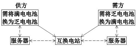
[0106] In battery swap mode, the electric vehicle registers through the server through the user terminal, and each electric vehicle ID is bound to its battery ID. When the electric vehicle is replaced, the battery ID needs to be re-bound; the electric vehicle can be used as the demand side to obtain full power through the battery exchange The battery can also be used as a supplier to provide a fully charged battery through battery replacement; when the electric vehicle is set as the supplier through the user terminal, the real-time information as the supplier will be sent to the server. Using the Internet of Things technology, the location of the electric vehicle, battery ID, Parameters such as battery power can be exchanged in real time through the server.

[0107] like figure 2 Shown is a schematic diagram of the electrical exchange method of the embodiment of the present invention. As shown in the figure, the demand s...

Embodiment 3

[0116] Embodiment 3: Method for switching electricity in mobile switching stations

[0117] like image 3 Shown is a schematic diagram of a method for exchanging electricity in a mobile interchange station according to an embodiment of the present invention. As shown in the figure, the demand side needs to replace the exhausted battery with a fully charged battery, and the supplier needs to replace the fully charged battery with an exhausted battery. Both the supplier and the demander exchange supply and demand information through the server through the user terminal to determine the mobile exchange. The location of the power station; when arriving at the mobile interchange power station, the supplier exchanges the fully charged battery with the demand side's exhausted battery, and the power is transferred from the supplier to the demand side through the method of swapping electricity.

[0118] Furthermore, the supply and demand sides exchange supply and demand information th...


PUM


Abstract

The invention relates to the field of electric vehicle charging and battery replacing, in particular to an electric vehicle battery replacing method, a battery replacing station and a battery replacing cabinet. The electric vehicle in the battery replacing mode is a demander and a supplier; the battery replacing station is a station where a supply party and a demand party exchange power in a powerexchange mode, and the supply party and the demand party exchange power and exchange power through the interchange power station. The electric energy is transferred from a supplier to a demander in the following turnover mode with a battery as a carrier: the electric energy of a power supply network supplements energy for a spent battery of the supplier through charging equipment to form a fully-charged battery; a supplier arrives at an interchange power station to exchange power; a fully-charged battery and a spent battery are exchanged; a demander arrives at an interchange power station toexchange power, a spent power battery is exchanged with a full power battery; and the supplier replaces the spent battery and then supplies energy to the charging equipment. The method has the beneficial effects that the investment of charging equipment and the capacity-increasing transformation cost of a power grid of a charging and replacing station in the prior art are reduced through interchanging electricity between electric vehicles; and the quantity of stock batteries in the charging and replacing power station and the occupied funds are reduced.

Description

technical field [0001] The invention relates to the field of battery charging and swapping for electric vehicles, in particular to a battery swapping method for electric cars, a swapping power station, and a swapping cabinet. Background technique [0002] In order to reduce the charging time of electric vehicles, the technology of replacing batteries to supplement electric energy has begun to be applied and promoted. The existing battery swap technology operation mode, the battery swap mode rides an electric car, and the battery swap mode electric vehicle usually adopts the vehicle-electricity separation mode. The car owner rents the battery from the battery operator, and when the battery is exhausted, it goes to the charging station to replace the battery. The way to replenish energy, the battery is circulated and shared between electric vehicles. [0003] In the existing battery replacement method, when the battery of the electric vehicle is exhausted, the user-end APP (i...

Claims


Application Information

Patent Timeline
IPC IPC(8): B60L53/80B60L53/66B60L53/30B60L53/00G07F15/00G07F17/00
CPCB60L53/00B60L53/30B60L53/66B60L53/80G07F15/005G07F17/0042Y02T10/70Y02T10/7072Y02T90/12Y02T90/14Y02T90/16
Inventor 杨天宝杨致远
Owner 杨天宝
Learn More