Intelligent tunnel pipeline detection vehicle
A technology for detecting vehicles and pipelines. It is used in motor vehicles, tracked vehicles, and fault detection according to conductor types. It can solve the problems of time-consuming and laborious manual maintenance, shorten the service life of cables, and difficult to locate and repair, and improve efficiency and accuracy. , to achieve the effect of protection and high degree of automation
- Summary
- Abstract
- Description
- Claims
- Application Information
AI Technical Summary
Problems solved by technology
Method used
Image
Examples
Embodiment 1
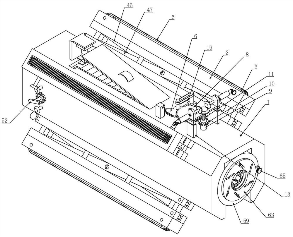
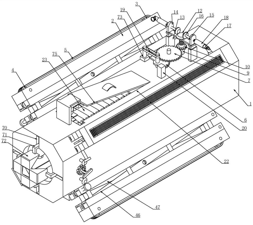
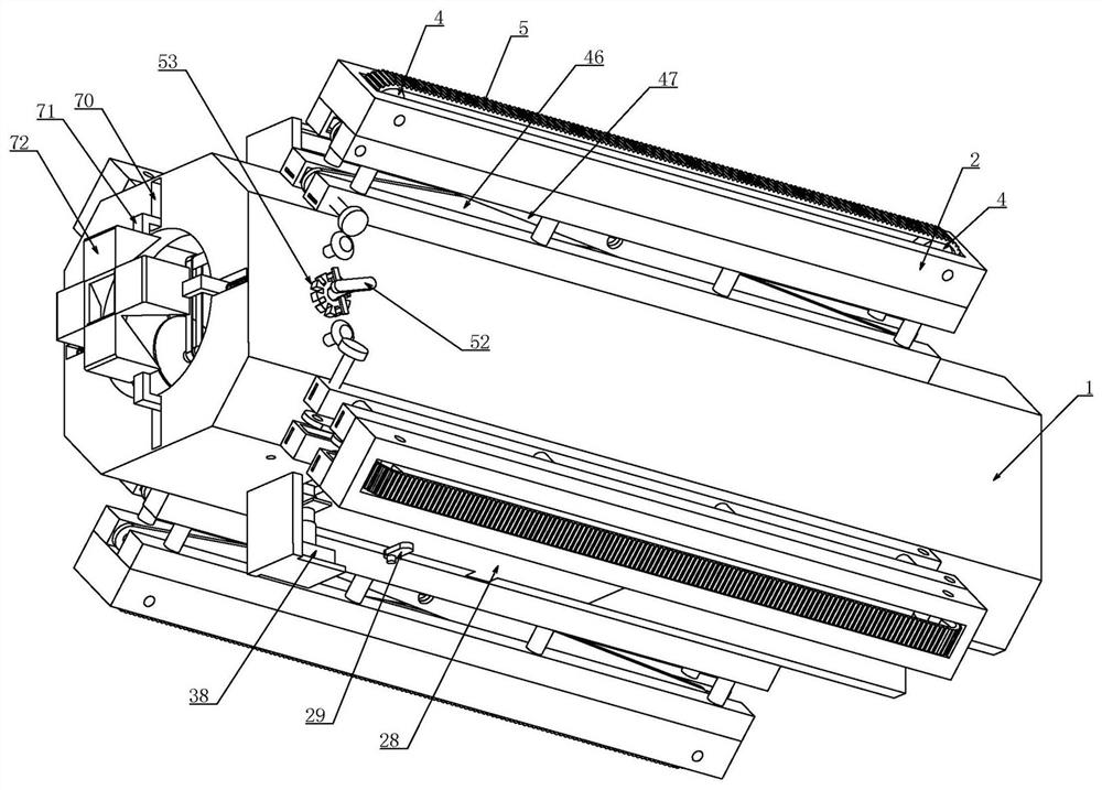
[0040] Embodiment 1, an intelligent tunnel pipeline inspection vehicle, includes a laterally transparent octagonal shell 1 structure, as described in the accompanying drawings, this octagonal structure is not a regular polygonal structure, and the four side walls of the front, rear, upper, and lower sides of the shell 1 The top is arranged in a rectangular shape, and the adjacent surfaces are arranged on inclined planes, and are arranged in a regular and symmetrical manner. It is characterized in that the four corners of the housing 1 are respectively connected with crawler boxes 2 arranged horizontally and matched with the inner wall of the pipeline. 2 is placed on the four inclined side walls of the shell 1, and the four sets of crawler boxes 2 are driven and connected by the lifting device installed on the shell 1, so that the lifting device can drive the four sets of crawler boxes 2 to expand or retract outwards at the same time. The lifting device drives four sets of crawl...
Embodiment 2
[0044] Embodiment 2. On the basis of Embodiment 1, the wire clamping device includes an inverted U-shaped first track 22 opened on the upper end of the housing 1. The first track 22 is horizontally slidingly fitted with multiple sets of upper layers. U-shaped button 23, the upper U-shaped button 23 is inverted in the first track 22, and the first track 22 is horizontally slidably connected to an upper U-shaped plate 24 placed on the right side of multiple groups of upper U-shaped buttons 23, Multiple groups of first springs 25 are connected between the upper U-shaped plate 24 and the first track 22, and the first springs 25 and the upper U-shaped plate 24 cooperate to squeeze and supplement the multiple groups of upper U-shaped buckles 23. The upper end of the housing 1 is provided with a first through hole 26 that matches the upper U-shaped buckle 23 and is placed at the end of the first rail 22. The first through hole 26 can enable the upper U-shaped buckle 23 to pass through...
Embodiment 3
[0048] Embodiment 3, on the basis of Embodiment 1, the lifting device includes fixed rods 44 installed on the four corners of the housing 1 and arranged laterally, and the fixed rods 44 slide along the direction of outward contraction or extension Cooperate with a support rod 45, so that the support rod 45 can only move along the height direction of the fixed rod 44, the left end of the support rod 45 is hinged with a first connecting rod 46, and the right end of the first connecting rod 46 Sliding fit is on the right end of fixed rod 44, and the left end of described fixed rod 44 is hinged a second connecting rod 47, and the right end of described second connecting rod 47 laterally slides and fits on the right end of support rod 45, and described first The connecting rod 46 and the second connecting rod 47 are arranged crosswise and hinged at the central intersection, thus forming a cross-type lifting structure. The hinge shaft of the second connecting rod 47 on the fixed rod ...
PUM
 Abstract
Description
Claims
Application Information
 - R&D Engineer
- R&D Manager
- IP Professional
- Industry Leading Data Capabilities
- Powerful AI technology
- Patent DNA Extraction
Browse by: Latest US Patents, China's latest patents, Technical Efficacy Thesaurus, Application Domain, Technology Topic, Popular Technical Reports.
© 2024 PatSnap. All rights reserved.Legal|Privacy policy|Modern Slavery Act Transparency Statement|Sitemap|About US| Contact US: help@patsnap.com


