Clutch

A clutch and clutch cover technology, applied in the field of clutches, can solve the problems of increased separation force, increased manufacturing cost, increased pressing force of diaphragm spring, etc., and achieves reduced outline size, light and labor-saving operation, and axial size. compact effect

Pending Publication Date: 2021-03-05
SCHAEFFLER TECH AG & CO KG
View PDF0 Cites 0 Cited by
  • Summary
  • Abstract
  • Description
  • Claims
  • Application Information

AI Technical Summary

Problems solved by technology

[0006] However, during the use of the traditional diaphragm spring clutch 9, when the friction plate will inevitably wear, the pressure plate 902 will move to the left, and at this time, the deformation of the diaphragm spring 904 will decrease, causing the diaphragm spring clutch 9 to move to the left. In use, the actual working pressing force has been increasing, so the separation force will also increase, which will inevitably sacrifice the user's operating comfort, and in order to solve this problem, an additional hydraulic booster will inevitably result in a clutch structure more complex and more expensive to manufacture
[0007] What's more, for current hybrid motor vehicles, a clutch needs to be installed on the axial outside of the clutch cover in order to achieve compactness, so as to be used as a switch clutch, but it is the same as a conventional clutch, and it is not It has a self-adjusting function, and there are also two major disadvantages: the pressing force of the diaphragm spring becomes larger when it is working, and the separation force of the operating clutch becomes larger.
[0008] Therefore, it is necessary to redesign the existing diaphragm spring clutch to overcome the problems that the pressing force of the diaphragm spring becomes larger during operation and the separation force of the operating clutch becomes larger

Method used


Image

  • Clutch
  • Clutch

Examples


Embodiment Construction

[0033] The following description of the embodiments refers to the accompanying drawings to illustrate specific embodiments in which the invention may be practiced. The directional terms mentioned in the present invention, such as "up", "down", "front", "back", "left", "right", "top", "bottom", etc., are only for reference to the attached drawings. direction. Therefore, the directional terms used are used to illustrate and understand the present invention, but not to limit the present invention. In addition, the embodiments described in the specific embodiments are only some of the embodiments of the present invention, not all of the embodiments. Based on the embodiments of the present invention, all other embodiments obtained by those skilled in the art without creative efforts fall within the protection scope of the present invention.

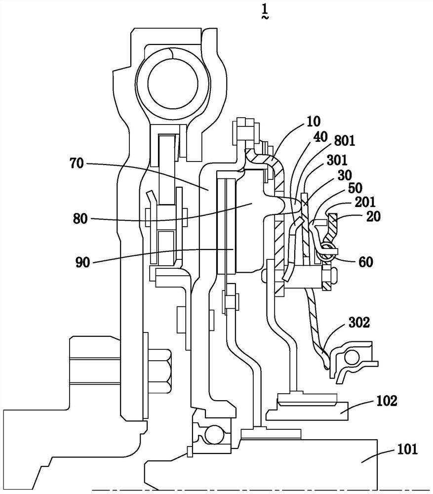
[0034] Please refer to figure 2 As shown, the clutch 1 of the present invention includes a clutch cover 10, a fixed plate 20, a diaphragm...


PUM


Abstract

The invention discloses a clutch. The clutch comprises a clutch cover, wherein a fixing plate, a diaphragm spring, a sensing spring and a wedge-shaped self-adjusting mechanism are arranged above the clutch cover; the wedge-shaped self-adjusting mechanism comprises an adjusting wedge ring and an adjusting spring; and the adjusting wedge ring is positioned between the diaphragm spring and the fixingplate. According to the clutch, the diaphragm spring is arranged on the axial outer side of the clutch cover, so that the axial size is compact, and the overall size of the whole clutch is reduced. Meanwhile, the clutch has a self-adjusting function, the finger tip position of the clutch is kept constant as much as possible in the whole service life period of the clutch and a clutch disc, the working pressing force is kept unchanged, the separation force is reduced, and the clutch is controlled conveniently in a labor-saving manner.

Description

technical field [0001] The present invention relates to a clutch for a motor vehicle drive system, in particular to a clutch for coupling an engine and / or an electric machine to a transmission of a motor vehicle. Background technique [0002] The clutch is a common part in mechanical transmission. It is located in the flywheel housing between the engine and the transmission. The clutch is fixed on the rear plane of the flywheel with screws. The output shaft of the clutch is the input shaft of the transmission. During the driving process of the car, the driver can step on or release the clutch pedal as needed to temporarily separate the engine from the transmission and gradually engage it, so as to cut off or transmit the power input from the engine to the transmission. The clutch is used to disengage or engage the transmission system at any time, so the basic requirements for the clutch are: smooth engagement, rapid and thorough disengagement, and convenient adjustment and r...

Claims


Application Information

Patent Timeline
IPC IPC(8): F16D13/58F16D13/75F16D13/70F16D13/68F16D13/38
CPCF16D13/38F16D13/585F16D13/68F16D13/70F16D13/757F16D2300/26
Inventor 范意中
Owner SCHAEFFLER TECH AG & CO KG
Why Eureka
Try Eureka